This thread has been locked.

If you have a related question, please click the "Ask a related question" button in the top right corner. The newly created question will be automatically linked to this question.

UCC28070: GDA, GDB status

Part Number: UCC28070

Tool/software:

Hi team,

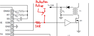
When VCC = 0V, are GDA and GDB pulled down to GND?
If I pull up GDA and GDB, will they not go high?

Best regards,

  • Hello Hirotsugu-san, 

    Within each gate-drive circuit of the UCC28070, there is a small self-biased P-channel or PNP transistor that forms a weak pull-down on GDx when VCC = 0.  It is capable of draining a low-level current (~2.5mA) to keep the main MOSFETs off in case of low-level transient disturbances on the AC line coupling through the Crss of the MOSFET. 

    These pull-downs are not capable of conducting high currents, and can be overloaded by high-current pull-ups and by low-impedance voltage sources.   
    They are internally disabled when VCC > ~2V is applied. 

    Regards,
    Ulrich

  • Hi Ulrich,

    Are there any conditions under which GDA and GDB will go into High-Z?

    What status will GDA and GDB be in the following conditions?

    - When VCC is between 2V and 8V

    - When disabled by the SS terminal

    Best regards,

  • Hi Hirotsugu-san, 

    There is no High-Z state for GDA or GDB in the UCC28070.  They are either driven on or driven off. 

    When VCC is < 8.8V and > 2V, the device is in the UVLO state and both GDx outputs are always driven low (off).  

    When disabled by the SS terminal, both GDx outputs are always driven low (off).  

    Regards,
    Ulrich

  • Hi Ulrich,

    Our customer is considering a protection circuit that will keep the PFC FET on during an abnormality and blow the fuse.

    Is this possible if there is a strong pull-up when VCC=0V?

    A weak pull-down circuit will be destroyed, but that's okay.

    Best regards,

  • Hi Hirotsugu-san,

    I understand your original question better now. 

    A strong pull-up from a special protection circuit can over come the UCC28070 gate-drive weak pull-down when VCC = 0V, but the pull-up will have to be very strong when 0V < VCC < 8.8 V. 

    The UCC28070 gate-drivers are not characterized to drive MOSFETs directly and it is expected that gate-drive ICs or buffer circuits are used to interface the GDx outputs to the PFC MOSFETs.  However, the GDx outputs really are actual gate-drive drivers adapted from a different IC and have significant pull-down strength when VCC is > ~2V.    It is not clear at what VCC voltage the pull-down strength becomes significant; probably somewhere between 1V < VCC <3V. 

    The exact value is not important, and may vary from IC to IC. What is important is that the special protection circuit may be required to act for some reason when VCC on UCC28070 is >0V, even if < 8.8V.  In that case, a direct protection pull-up will face a fairly low-impedance pull-down from the UCC28070 driver outputs.   

    To avoid this, I suggest to insert a 1kR resistor in series with each GDx so that the protection pull-up only has to drive a 1kR load (approximately).
    The 1kR series resistors will not produce significant time delay for normal PWM signals to the gate-driver IC due to input-pin capacitance (typically 5pF, for example).  And 1kR will limit the current so that the UCC28070 is unlikely to be damaged. 

    Lower values of series resistors will reduce PWM time delay even more, but will allow higher pull-down driver current.  At some lower resistance, the risk of gate-drive damage becomes significant.  Your customer can make the trade-off between minimizing PWM delay time and minimizing protection circuit pull-pup strength. 

    Regards,
    Ulrich