This thread has been locked.

If you have a related question, please click the "Ask a related question" button in the top right corner. The newly created question will be automatically linked to this question.

LM5118: Inductor design

Part Number: LM5118

Tool/software:

Hi TI community,

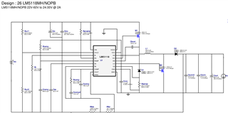
I’m working on an LM5118 design with the following specifications and I’m having a hard time finding a suitable inductor. I’m not that experienced in power electronics and hope someone would like to share their experience.

Specification

  • Vout = 24V
  • Vin = 22V to 60V
  • f = 300kHz
  • Maximum load current = 2A
  • Minimum load current (CCM operation) = 200mA (10% of max load)

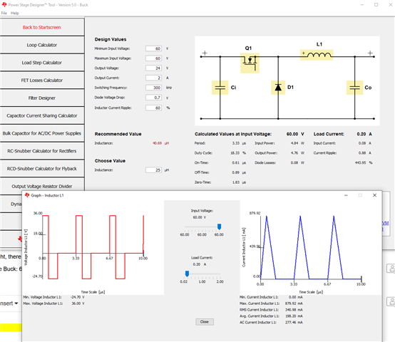
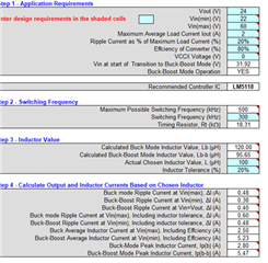
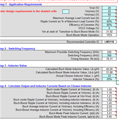
Using the Excel tool (snvu065a) and the datasheet, I find an inductor value of 100uH.
However, the peak current in the inductor is around 5.5A, which is pretty high for an inductor of this size. I’m unable to find a suitable inductor with a saturation current higher than or equal to the peak current of 5.5A. Any suggestions?


Are my design specifications too tight or is there something that I have misunderstood?

The Webench power designer suggests a 33uH inductor. This results in an inductor ripple of 1.45A at worst-case Vin. This will limit the minimum current in CCM to 1.45/2 = 0.725A.


This, from my perspective, is a high current as a minimum, when the maximum load is 2A.
The nominal current of my application is around 200mA. Can the converter operate in DCM at this current? Is it bad design to run in DCM mode?  What are the disadvantages of this?


Any advice on inductors, advantages, and disadvantages of the design is appreciated.


Best Regards,
Sam

  • Hi Sam,

    thanks for reaching out.

    Please give me some time to look into it.

    I will come back with an answer until the end of the week.

    Best regards

    Moritz

  • Hi Sam,

    By setting the allowed ripple current in the excel sheet a bit higher, you will also get in the range of around 30uH for the inductor.
    This is also a value i would recommend (something between 25-30u).

    The also the choice for a sufficient current should be bigger.

    This, from my perspective, is a high current as a minimum, when the maximum load is 2A.

    1.45A is only the ripple current in this case. The RMS is around 5.5A.
    The load is 2A, yes, but at 60V. The input min is only 22V. So the current in the input hs to be much higher.

    Best regards

    Moritz

  • Hi Moritz,

    Thank you for the comment. I will go with a inductor of around 25-30uH.

    Do you have any comments on the DCM mode at 200mA? Is the controller able to provide this low power sufficiently in DCM mode? I have a hard time finding information about controllers working in DCM mode.

    Best regards,
    Sam

  • Hi Sam,

    I am not sure if i got the DCM question right.

    Do you want the controller to operate in CCM down to a load of 200mA and then switch to DCM?

    For such calculations i recommend to use the power stage designer: https://www.ti.com/tool/POWERSTAGE-DESIGNER

    Best regards

    Moritz

  • Hi Moritz,

    No, I was more concerned about the consequence of a light load when allowing a higher ripple current. 
    I will lower the inductance and thereby allow more ripple(1.45A) at Vin_max.
    What happens if I have 60 volt input and the load is only 200mA? From my understanding the controller will now operate in DCM as the load is below the minimum current for CCM(1.45/2=725A). Is this correctly understood?
    Will the controller still be able to regulate the output?

    Thanks for your time.


    Best regards,
    Sam

  • Hi Sam,

    At Vin=60V, Iload= 0.2A, the device will operate in DCM, yes. To operate in CCM under 60V vin, you would need to have a min output current of ~1A. (assuming L=25uH) --> All this can easily be checked using the power stage designer.

    DCM is not a problem. It is a normal condition. When a design is made for a certain load, there is always a point when the load is tooo low to stay in CCM.
    CCM and DCM operation both have advantages and disasvantages but in both a normal regulation is possible.

    Best regards

    Moritz

  • But if, for some reason, iti is required to operate in CCM also with a load of 200mA,
    the inductor has to be very big (110uH) or the switching frequency has to be higher.

  • Hi Moritz,

    Thank you for the answer. Would you please be so kind to show me with a screenshot how you use the power stage designer for this? I cant seem to find the non-inverting buck boost topology. 

    Best regards,
    Sam

  • This will be to big of an inductor and not practically possible.

  • Hi Sam,

    You are right, there is no buck boost in the power stage designer. But you can have a look at the corner cases.

    In this case Buck: 60VIN to 24Vout:

    Best regards

    Moritz

  • Hi Moritz,
    Thank you for your answers.
    A quick follow up question:
    Do you have any resources( or recommendations) where I can learn more about the advantages and disadvantages of CCM and DCM mode?

    Best regards,
    Sam

  • Hi Sam,

    I can recommend the following document: https://www.ti.com/download/trng/docs/seminar/Topic_3_Lynch.pdf

    There is also a section about DCM and CCM. Also you can find a lot of information online, with really good tables that compare advantages and disadvantages.

    Examples for differences are in Inductor size, ripple current, EMI, rectifier current, transient response...

    Best regards

    Moritz