This thread has been locked.

If you have a related question, please click the "Ask a related question" button in the top right corner. The newly created question will be automatically linked to this question.

TPS650860EVM-116: Device Description File Not Working

Part Number: TPS650860EVM-116
Other Parts Discussed in Thread: IPG-UI, BOOSTXL-TPS650861, USB2ANY, , MSP430F5529, TPS65086, TPS650861

Tool/software:

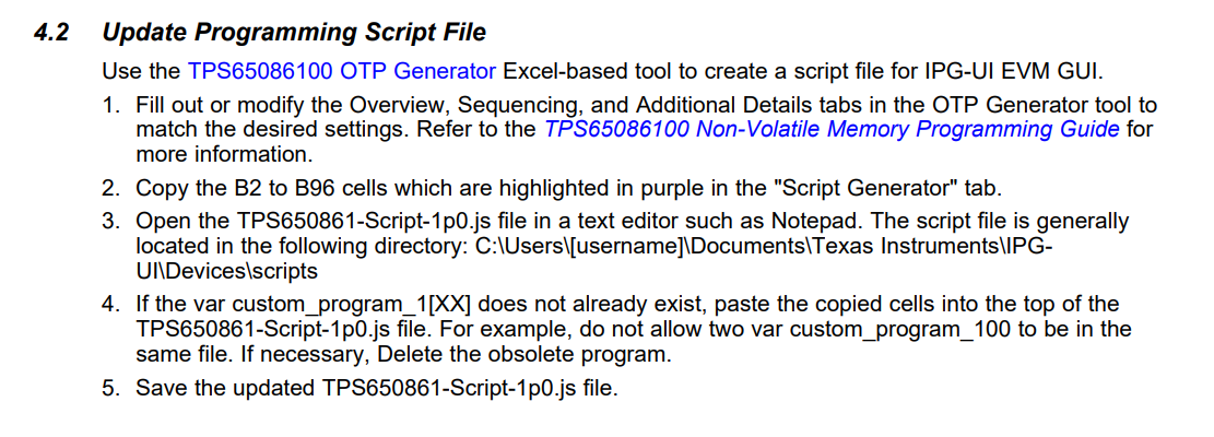
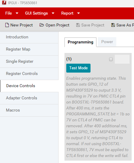
I am attempting to use the TPS65086100 OTP Generator V2p5 to import into the IPG-UI in order to program the above EVM. The JSON (collated from the "Using IPG-UI" tab in the "Script Generator" sheet of the calculator, see the JSON below) fails to import, see the error below.

  1. What is the expected structure of the JSON accepted by the IPG-UI, is there documentation that indicates what structure it should follow
  2. Is there a better method to generate the JSON from the Generator that I am missing

"The file selected does not appear to be a valid device description file. Please verify the file and try again. If this error continues it could be due to a file that is not compatible with this version of the GUI. Please check www.ti.com for updated device description files"

The related device description file (copied from the generator):

var custom_program_100 = [
                   {group: 'PART_NUMBER', value: 0x100},
                   {register: 'DEVICEID2', value: 0x01},
                   {register: 'BUCK1CTRL', value: 0xE8},
                   {register: 'BUCK2CTRL', value: 0xDC},
                   {register: 'BUCK3DECAY', value: 0x38},
                   {register: 'BUCK3VID', value: 0x38},
                   {register: 'BUCK3SLPCTRL', value: 0x38},
                   {register: 'BUCK4CTRL', value: 0x0E},
                   {register: 'BUCK5CTRL', value: 0x0E},
                   {register: 'BUCK6CTRL', value: 0x0C},
                   {register: 'LDOA2CTRL', value: 0x0C},
                   {register: 'LDOA3CTRL', value: 0x0C},
                   {register: 'DISCHCTRL1', value: 0x00},
                   {register: 'DISCHCTRL2', value: 0x00},
                   {register: 'DISCHCTRL3', value: 0x00},
                   {register: 'PG_DELAY1', value: 0x00},
                   {register: 'BUCK1SLPCTRL', value: 0xE8},
                   {register: 'BUCK2SLPCTRL', value: 0xDC},
                   {register: 'BUCK4VID', value: 0xA8},
                   {register: 'BUCK4SLPVID', value: 0xA8},
                   {register: 'BUCK5VID', value: 0x26},
                   {register: 'BUCK5SLPVID', value: 0x26},
                   {register: 'BUCK6VID', value: 0xA0},
                   {register: 'BUCK6SLPVID', value: 0xA0},
                   {register: 'LDOA2VID', value: 0x00},
                   {register: 'LDOA3VID', value: 0x00},
                   {register: 'BUCK123CTRL', value: 0x20},
                   {register: 'PG_DELAY2', value: 0x00},
                   {register: 'SWVTT_DIS', value: 0x00},
                   {register: 'I2C_RAIL_EN1', value: 0x00},
                   {register: 'I2C_RAIL_EN2', value: 0x00},
                   {register: 'PWR_FAULT_MASK1', value: 0x00},
                   {register: 'PWR_FAULT_MASK2', value: 0x20},
                   {register: 'GPO1PG_CTRL1', value: 0xFE},
                   {register: 'GPO1PG_CTRL2', value: 0xFF},
                   {register: 'GPO4PG_CTRL1', value: 0xCC},
                   {register: 'GPO4PG_CTRL2', value: 0xFF},
                   {register: 'GPO2PG_CTRL1', value: 0xFC},
                   {register: 'GPO2PG_CTRL2', value: 0xFF},
                   {register: 'GPO3PG_CTRL1', value: 0xEC},
                   {register: 'GPO3PG_CTRL2', value: 0xFF},
                   {register: 'MISCSYSPG', value: 0xFF},
                   {register: 'VTT_DISCH_CTRL', value: 0x4F},
                   {register: 'LDOA1_SWB2_CTRL', value: 0x00},
                   {register: 'BUCK1_CTRL_EN1', value: 0xFF},
                   {register: 'BUCK1_CTRL_EN2', value: 0xFB},
                   {register: 'BUCK1_CTRL_EN3', value: 0x00},
                   {register: 'BUCK2_CTRL_EN1', value: 0xFE},
                   {register: 'BUCK2_CTRL_EN2', value: 0xCB},
                   {register: 'BUCK2_CTRL_EN3', value: 0x00},
                   {register: 'BUCK3_CTRL_EN1', value: 0xEF},
                   {register: 'BUCK3_CTRL_EN2', value: 0x63},
                   {register: 'BUCK3_CTRL_EN3', value: 0x00},
                   {register: 'BUCK4_CTRL_EN1', value: 0xEF},
                   {register: 'BUCK4_CTRL_EN2', value: 0xE3},
                   {register: 'BUCK4_CTRL_EN3', value: 0x00},
                   {register: 'BUCK5_CTRL_EN1', value: 0xFD},
                   {register: 'BUCK5_CTRL_EN2', value: 0x63},
                   {register: 'BUCK5_CTRL_EN3', value: 0x00},
                   {register: 'BUCK6_CTRL_EN1', value: 0xCC},
                   {register: 'BUCK6_CTRL_EN2', value: 0xC3},
                   {register: 'BUCK6_CTRL_EN3', value: 0x00},
                   {register: 'SWA1_CTRL_EN1', value: 0xEF},
                   {register: 'SWA1_CTRL_EN2', value: 0x03},
                   {register: 'SWA1_CTRL_EN3', value: 0x00},
                   {register: 'LDOA2_CTRL_EN1', value: 0xFF},
                   {register: 'LDOA2_CTRL_EN2', value: 0x43},
                   {register: 'LDOA2_CTRL_EN3', value: 0x00},
                   {register: 'LDOA3_CTRL_EN1', value: 0xFF},
                   {register: 'LDOA3_CTRL_EN2', value: 0x03},
                   {register: 'LDOA3_CTRL_EN3', value: 0xC0},
                   {register: 'SWB1_CTRL_EN1', value: 0xDF},
                   {register: 'SWB1_CTRL_EN2', value: 0xE3},
                   {register: 'SWB1_CTRL_EN3', value: 0x00},
                   {register: 'SWB2_LDOA1_CTRL_EN1', value: 0xFF},
                   {register: 'SWB2_LDOA1_CTRL_EN2', value: 0xE3},
                   {register: 'SWB2_LDOA1_CTRL_EN3', value: 0x00},
                   {register: 'OTP_RSVD_38_28', value: 0x18},
                   {register: 'SLP_PIN', value: 0x00},
                   {register: 'OUTPUT_MODE', value: 0x00},
                   {register: 'OTP_RSVD_38_2C', value: 0xA1},
                   {register: 'OTP_RSVD_38_2E', value: 0xAA},
                   {register: 'OTP_RSVD_38_32', value: 0x61},
                   {register: 'OTP_RSVD_38_34', value: 0xAA},
                   {register: 'OTP_RSVD_38_38', value: 0x61},
                   {register: 'OTP_RSVD_38_3A', value: 0xAA},
                   {register: 'OTP_RSVD_38_44', value: 0x05},
                   {register: 'OTP_RSVD_38_48', value: 0x25},
                   {register: 'OTP_RSVD_38_4C', value: 0x25},
                   {register: 'OTP_RSVD_38_53', value: 0xA8},
                   {register: 'I2CADDRESS', value: 0x00}];
  • Hi Helios,

    The contents of the script generator should be copied into the existing "TPS650861-Script-_p_.js" file located in the IPG-UI folder on your computer drive
    (full path in bullet 3 of the photo below)

    Please follow the steps outlined in the 4.2 section of the BOOSTXL-TPS650861 EVM User’s Guide:
    I understand you are using a different EVM , but the procedure should be the same.

    The TPS65086100 Programming Guide is another document that may have additional programming instructions.

    Best Regards, 
    Sarah

  • Thanks for the update. I ended up finding the instructions above and successfully loaded my configuration from the OTP generator.

    I have a seperate issue (can open another forum post if necessary) where I cannot put the PMIC into "Test Mode" / Programming Mode. Following Step 8 in the "Programming Steps" section of the BOOSTXL-TPS650861 EVM User’s Guide.

    Receive 2 messages:

    1. Programming state enabled

    2. USB2ANY Failure: -44 ERR_I2C_ADDR_NAK
    According to USB2ANY spec: Address not acknowledged (NAK)

    In the "Device Controls" section the Test Mode description text (quoted below) refers to the BOOSTXL-TPS650861 board, while I am using a TPS650860EVM-116. Is there different device support that needs to be installed for this EVM? If not, than how can I enter Programming Mode on my EVM?

    Test Mode description in "Device Controls" menu:

    (1) Test Mode: Enables programming state. This button sets GPIO_12 of MSP430F5529 to output 3.3 V, resulting in 7V on PMIC CTL4 pin on BOOSTXL-TPS650861 board. After 400 ms, it sets the PROGRAMMING_STATE bit = 1b so 7V on CTL4 of PMIC can be removed. After 400 additional ms, it sets GPIO_12 of MSP430F5529 to output 0 V, returning CTL4 to normal. If not using BOOSTXL-TPS650861, 7V must be applied to CTL4 first or else the write will fail.

  • Hi Helios,

    Are you providing power to the EVM board in any way? I have seen this NAK error when power is not sufficiently provided. 
    Please ensure the sufficient VSYS is being provided.

    I also want to confirm that even though you are using the TPS650860EVM-116, have you swapped the main IC with the User Programmable TPS650861 ?

    If not using BOOSTXL-TPS650861, 7V must be applied to CTL4 first or else the write will fail.

    For programming, a stable 7V needs to be provided to CTL4 pin. The BOOSTXL-TPS650861 accomplishes this internally with a MUX
    For your case, you would just need to ensure that you can provide 7V to this pin. 

    Best Regards, 
    Sarah

  • 1. I was providing 8V to VSYS, which falls above the minimum 5.4V indicated on the TPS65086x EVM User's Guide

    2. What do you mean swapped the main IC? The IC on the EVM is a TPS650860A0. My design uses a TPS65086100, and this is the sequence and OTG values that I am attempting to validate - is this the incorrect kit?

    3. I'm unable to find the external CTL4 pin on which to provide 7V exposed on the EVM -- I can only see the related TP49 / DIG_1P8V. 

    Considering that the datasheet also states that 7V should only be provided for under a minute or so, how would you recommend testing this? 

    Thank you,
    Helios

  • Hi Helios, 

    The IC TPS650860A0 , that comes on the TPS650860EVM-116 is not user-programmable.

    The TPS650861 is the user-programmable version, and is the intended device for the TPS65086100 OTP Generator.

    I believe you may be using the wrong kit for your design. You would need a TPS650861, and this would be more convenient to program it with the BOOSTXL-TPS650861 EVM. 

    Apologies for the confusion. Hope this helps to clarify.

    Best Regards. 
    Sarah Lao 

  • Hi Sarah,

    To be clear, there is no way to test our program / desired startup sequence and PMIC parameters on the TPS650860A0 PMIC (as part of the TPS650860EVM-116)? Can you help me understand the difference between them, and what it means to be user-programmable? 

    I ask because using the IPG-UI I seem to be able to modify register values in the TPS650860A0 PMIC currently on the board.

    Thanks,
    Helios

  • Hi Helios, 

    Yes, I can explain the difference between the two PMICs.

    The TPS650860A0 is software-configurable, but not what we consider "User-programmable". This means you are able to interact with it via the IPG-UI and modify the register values via I2C.
    However, you are not able to burn these values into the OTP, meaning these register values will reset back to the default factory settings upon power down/power on. These settings will need to be programmed each time on power up. 

    In other words, you are able to modify the settings in the GUI, but you cannot permanently program the IC to hold these values. 
    This should be OK for testing purposes, if you are wanting to just observe how your functions operate on the PMIC. If your system is able to use I2C to write these register values, then this is OK. And in this case, you would not need to set the PMIC in programming state, since you are just writing commands via I2C, and not permanently burning a new OTP.

    If your system does not have I2C capability, then you would want the user-programmable version so that you are able to program these values beforehand, and do not need to perform any writes upon startup. 

    For the TPS65086100, this is software-configurable, user-programmable. This means that you are able to program your own default settings (with the OTP Generator) and burn this into the IC by setting the device in the programming mode, and so that these register values are saved and automatically loaded upon powering on the PMIC. 

    Let me know if I can explain anything further.

    Thanks, 
    Sarah

  • Hi Sarah,

    Thank you for the clarification, we will move forward with testing on the TPS650860A0 as best possible.

    I work for Disguise that is using the PMICs for products currently in development -- would it be possible to get a point of contact in order to receive information like this ahead of time for future development? This would be very useful, and I am happy to escalate. 

    Looking forward to hearing from you,
    Helios

  • Hi Helios, 

    Of course, I've reached out to the marketing team for a point of contact I can direct you towards.
    I'm still waiting to hear back, but I will let you know as soon as I get that information for you. 

    Thanks, 
    Sarah

  • Hi Sarah,

    We're moving forward with using the existing EVM for testing, and our own PSU dev boards to validate sequence behaviour after programming, so I think this thread should be closed. 

    Perhaps the info pages for the EVM could be clarified to indicate the development flow a bit better. For any updates please contract me at helios.lyons@disguise.one.

    Best,
    H.

  • Afternoon Sarah, 

    I am reviving this thread as we are having further issues using standard I2C hardware to write to the TPS65086100 PMIC on our development board. Are there any particularities with timing that should be adhered to? The issues are quite unusual, as the registers can be read (inconsistently) and not written to. Considering the PMIC is on our board with an exposed I2C header, would you recommend any TI hardware for interfacing with it?

    Thank you,
    H.

  • Hi Helios, 

    Here are the expected timing values for the I2C interface:

    Can you clarify what mircocontroller/hardware you are currently using on your development board to perform I2C read/writes?

    And is there a specific register(s) which you are having trouble writing to? The inconsistent reading is strange,
    but are you able to cross-reference your registers with the register map listed in section 5.11 of the datasheet,
    to ensure they are on the list of registers that can be accessed without being in programming mode?

    Best Regards, 
    Sarah

  • We are using a Raspberry Pi 4 for I2C comms, which has worked with many other devices. We can read registers correctly, including those at address 0x38 when CTL4 is set to 7V (programming mode) but cannot write to most registers. The IRQ mask register is writable, but the BUCK1CTRL register remains unchanged despite attempts to write to it. 

    We also just received the MSP430F5529 board and flashed it with the USB2ANY firmware. It recognises the PMIC, and we can use IPG-UI to read register values, but exhibits the same write issues. 

    We suspect that there is something like a GPIO line that needs to be driven in order to entire programming mode, or there is a correct series of operations. It essentially seems to be write-protected, but there is no indication this should be the case in the documentation. We are finding the quantity of documentation between the same range of products to be problematic, and would appreciate guidance in navigating this to program our PMIC.

    Looking forward to hearing from you,
    H.

  • Hi Helios, 

    Are you following the steps in the TPS65086100 Non-Volatile Memory Programming Guide:

    Specifically, the writing to the OTP_CTRL1 register, PROGRAMMING_STATE bit? This could be preventing the writes to the 0x38 registers. 

    "In order to access the registers in device address 0x38 the TPS65086100 must first be put into programming mode by writing the PROGRAMMING_STATE bit in the OTP_CTRL1 register to 1b. In order to access this register, 7V must be placed on the CTL4 pin. Once the PROGRAMMING_STATE bit in the OTP_CTRL1 register is set to 1b, remove the 7V from the CTRL4 pin. Once this is done all of the registers in the device can be accessed."

    I apologize for the inconvenience in the documentation, and I agree that it is difficult to navigate.
    I will push for getting our document library cleaned up and organized better.

    Let me know if you are still unable to write to these registers.

    Best Regards, 
    Sarah 

  • Hi Sarah,

    Apologies for the delay. I have secured a copy of the PSU dev board and am indeed unable to write these registers. My setup is IP-GUI on laptop <-> USB2ANY interface adapter <-> PMIC (on PSU dev board). I cannot follow the official procedure as the PMIC is already soldered to the board. That said I have made an external switch board to ground the CTL pins and apply 7V to CTL4. The current issue is I am not getting any I2C comms out of the USB2ANY interface adapter I2C lines. Do I need to use it in conjunction with the BOOSTXL-TPS650861 or some related part? 

    As a brief update, I am currently using a Raspberry Pi and able to see the device at 0x5e, and the device at 0x38 when 7V is applied to CTL4. However the programming state is not persistent, and when I write the value 0x80h to the OTP_CTRL1 register in order to set the PROGRAMMING_STATE bit I cannot get the value to persist, and thus the device to stay in programming mode.

    Looking forward to hearing from you,
    Helios

  • Hi Helios, 

    The programming setup is easier with a BOOSTXL-TPS650861 or socketed board, rather than a soldered-on board.
    But t
    he USB2ANY / IPG-UI setup should also be able to work on your custom board.
    Is the GUI recognizing the device as Hardware Connected?

    From there, using the IPGUI steps should follow the same as listed in section 4.4 of the BOOSTXL-TPS650861 EVM User’s Guide, particularly paying attention to the Device Controls tab instructions in Step8.

    Are you able to see if using the "Test Mode" button has more success in setting the PROGRAMMING_STATE bit ? 

    Best Regards, 
    Sarah

  • IP-GUI is recognising the USB2ANY as "Hardware Connected". When I hook up my logic analyser to the I2C output of the USB2ANY nothing is being written through, which means it cannot be used to program the PMIC. For some reason I can read values from the USB2ANY.

  • Hi Helios, 

    When you say that "nothing is being written", are you seeing absolutely no toggles on the logic analyzer when attempting to write?
    This may be an indicator of issues with the host device, not the PMIC. 

    Can you clarify if this is the issue?

    Best, 
    Sarah

  • Apologies if I was unclear, yes I confirm I am seeing no toggles on the USB2ANY I2C lines when writing values with IP-GUI (verified with external Salae logic analyser). I can also "read" from the USB2ANY device (not the PSU board connected via I2C) -- it is as if there is a buffer in USB2ANY that contains some relevant register values.

  • Hi Helios, 

    Are you able to share some images of your physical setup, along with what you are seeing on the IPGUI?
    Just so I can get a better understanding here.

    Are any errors appearing in the top right corner when you get a failed attempt to write?
    I also want to confirm the I2C address in the Register Map tab is set to 0x5E ?

    Best Regards, 
    Sarah

  • Hi Sarah -- apologies for the lack of reply, I ended using I2C directly to program the PMIC, which worked as expected. There were no errors showing up, and the I2C address was 0x5E, I was just getting no I2C output from the Interface Adapter at all.

  • Hi Helios, 

    Glad to hear that the I2C is now working properly. Thank you for the update!

    Best,
    Sarah