This thread has been locked.

If you have a related question, please click the "Ask a related question" button in the top right corner. The newly created question will be automatically linked to this question.

TPS929240EVM: Device support Implementing FlexWire Protocol Over CAN Interface

Part Number: TPS929240EVM
Other Parts Discussed in Thread: HALCOGEN,

Tool/software:

Hello,

We are experiencing issues while implementing the FlexWire protocol over a CAN interface to communicate with our driver. Below is a detailed description of the problem:

Context:

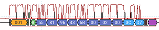
We have successfully implemented the FlexWire protocol and connected it via a serial interface (SCI) from a Hercules TMS570LC43. Through this method, we send a synchronization byte (sync), the device address (dev addr), register address (reg addr), and a calculated CRC. Using this serial interface, we are able to control the drivers without any issues.

Issue with CAN Protocol:

When we attempt to perform the same communication using the CAN protocol, we encounter issues. We have configured the CAN bus parameters using Halcogen, including the ID, frequency, and other relevant settings. On the CAN bus (CAN_H and CAN_L), we can observe the messages with the configured parameters as expected. The data bytes include the synchronization byte, device address, register address, and the calculated CRC, just like with the serial interface. However, the drivers do not respond to these messages when communicated over the CAN bus.

We would like to know the correct procedure for utilizing the CAN interface with the FlexWire protocol. Specifically, are there additional considerations or configurations required for the CAN protocol that differ from the serial implementation? Could there be any timing, message framing, or data interpretation issues specific to the CAN interface that we might be overlooking?

Any guidance on how to properly implement the FlexWire protocol over the CAN interface to ensure successful communication with the drivers would be greatly appreciated.

Thank you for your support.

  • Hello, 

    TPS929240 should respond if receives right data bytes.

    Are you testing with TPS929240EVM board? Pls check if Jumper Configurations is correct. (Refer to Figure 3-4. TPS929240EVM Jumper Configurations with TPS929120CANEVM Connected). 

    If jumper configuration is correct, you may capture RX data with digital analyzer and share with me. 

    Between two master frames, you need to have time delay considering TX loopback. For example, 2bytes (status+crc bytes) delay for write command and N+1 bytes (data + crc byte) delay for read command. 

    There is sample code based on MCU430 that you can refer to and you can download it from TI website. 

  • Hello,

    Yes, I am currently testing the TPS929240EVM, and I have followed the jumper configuration as outlined in the user guide, specifically Figure 3-2: TPS929240EVM Jumper Configurations without TPS929120CANEVM Connected. The CAN transceiver is successfully receiving the CAN frames at the pin RXD from the TCAN1042HGDRQ1

    I am attempting to send the CTRLGATE register to unlock the device, but I am not receiving any response after sending the initial message. I have confirmed that the CAN frame is reaching the device with the correct configuration, but the expected response or acknowledgment from the driver is missing.

    Additionally, I have ensured that the jumper settings are correct for the setup I am using. Could you provide more insight into why the device might not be responding to this command? Is there a specific delay, timing, or additional configuration that I might need to consider when unlocking the device via CAN protocol?

    Also, I will capture the RX data with a digital analyzer as you suggested and share it with you to help diagnose the issue further.

    Thank you for your assistance.

  • Please kindly send me the data that you captured on RX/TX so that I can have more idea about what is going on. 

  • Hi, those are the captures that I got with the digital analyzer.

    The first one is the CAN frame, with the ID: 0x01. in the data, the firts byte is the sync byte, the the second byte is the dev addres, which is the write bit (0x80) or device addres (0x01) as result in 0x81 in data byte 2. Then the register addres, in this case, I wanted to write the control gate (0x96), then the data (0x43) and last byte, is the CRC calculated (0x6B) and checked with the TPS tool. The 3 bytes more are the rest of the can frame protocol. 

    the second image, is the frame sent by the Hercules TMS570 over the CAN bus without aresponse. The master frame at 500kb/s never get the response, as you can see at the image the time delay should be more than the required

    Please find both image attached into the zip

    .Log_can_time.zip

  • I'm not sure the location on the board that you take measurement. Is it on Rx pin? While it's definitely not the frames that TPS929120 can detect if shown as below. You need to check the data quality. For me, I can't get the target data from below waveform. 

  • Hi,

    in pourple, the 0x55 is the sync byte. the 0x81 is the write bit || device addres 0x01. The 0x96 is the register I wanted to write. 0x43 is the data and finally the 0x6B is the crc. The 0xD7 in blue, its the CRC calculated by the CAN protocol frame

  • What is red curve? can you share me the original file? thanks! 

    What is 001, 8? what is 00 02 00 3C, D7 right after CRC - 0x6B?

    You should wait for 2bytes( status+ CRC) if didn't disable ACK; 

    TPS929240 uses flexwire protocol (check details in datasheet)