TPS25947: 12 volt input support and power sequencing

Part Number: TPS25947

Tool/software:

I need a solution that allows a user to attach a 12 volt plug to my board and have a  circuit will protect against over voltage, short circuits, and reverse voltage. Once power is applied and the level is valid, the circuit will enable my the 3v3 regulator (TPS62130ARGTR) in my design.  Once the 3v3 is up, other regulators will turn and the total current draw should be around 3-4 amps.  I think that the TPS25947 will do what I want but I have a few questions:

1) The power supply is a wall wart and has about a 3 foot cable. The input caps on my buck regulator are ceramic so I have added a 330 uf polymer cap so that the input of the regulator doesn't oscillate. If I put the TPS25947 down, would the 330 uF need to be moved to the input side of TPS25947 or would I need to put one on each side? 

2) The user will plug the wall wart in first and then attach it to the board. I believe this is a hot plug event, is there anything special that needs to be done to support this?

3) The platform being design is for development. Is there another version of this device that is in a package which can be hand soldered so it is repairable in a lab? 

4) After the TPS25947 comes up, do you have a part that will sequence 4 supplies?

Thanks

Bill

  • I came across the document "11 ways to protect your power path" and it looks like the TPS25942, TPS25944 series of devices is a better choice. They give me a larger package, active high PGOOD, and the current/voltage protection I am looking for. 

  • Hi Bill,

    Thank you for checking these eFuses. 

    1) The power supply is a wall wart and has about a 3 foot cable. The input caps on my buck regulator are ceramic so I have added a 330 uf polymer cap so that the input of the regulator doesn't oscillate. If I put the TPS25947 down, would the 330 uF need to be moved to the input side of TPS25947 or would I need to put one on each side? 

    Yes, due to long cable, you will have high transients which will most likely exceed the abs max of these eFuses ( valid for all the devices you mentioned). You will need these bulk cap and more importantly decoupling ceramic cap near the input of device to prevent the abs max violation. 

    2) The user will plug the wall wart in first and then attach it to the board. I believe this is a hot plug event, is there anything special that needs to be done to support this?

    In case of hot-plug, you will get transient spike. Add TVS diode to clamp them within the limit (valid for both devices)

    The platform being design is for development. Is there another version of this device that is in a package which can be hand soldered so it is repairable in a lab?

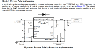
    Most of the new eFuses are in small packages only. When you mentioned you need reverse voltage protection, do you want to block reverse current protection or do you want to prevent any damage in case of board is plugged in incorrect orientation (reverse polarity protection). I think you need this RPP. 

    TPS25942/4 do not have RPP and you will have to add a diode to implement this but they are good options here (bigger packages compared to other eFuses) 

    4) After the TPS25947 comes up, do you have a part that will sequence 4 supplies?

    We can implement power mux using these 4 eFuses. Please check the application section of datasheet for TPS25947. 

    Best Regards,
    Arush

  • Hey Arun, thank you for getting back to me.

    The wall wart for input power has a 1 meter cable using 16 awg wire. This translated to about 1.5 uh of inductance. I will move a single 330 uf capacitor along with a couple of 1206 ceramics to the input of the switch. 

    Using equation 37: Vspike = Vin + Iload*sqrt(Lin/Cin)  = 12 + 4 * sqrt(1.5e-6/300e-6)  = 12.7 V

    This assumes I have a 4 amp transient which will not be the case. My worst case current load is 4 amps.

    I expect that I won't see transient current over 1 amp, that would imply a 12 watt change in the load.

    12 + 1 * sqrt(1.5e-6/300e-6)  = 12.07 V

    Am I correct thinking that 12.07 - 12 = 0.07 volt difference and since the device can withstand 22 volts input, a tvs diode is not really needed?

    Bill

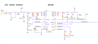
  • Hey Arun, I add the TVS diode, could you please review my schematic? 

    thanks

    Bill

  • Hi Bill,

    The schematic looks good.

    Best Regards,
    Arush