This thread has been locked.

If you have a related question, please click the "Ask a related question" button in the top right corner. The newly created question will be automatically linked to this question.

TPS61289EVM: Using as backup circuit with SuperCap charging/discharging solution

Part Number: TPS61289EVM
Other Parts Discussed in Thread: TPS61289, TPS61094, , TPS61299

Tool/software:

Hi TI Team,

I was searching for a bidirectional buck/boost converter with a very low VIN for the backup power, since we like to use only one SuperCap (max. 2.7 V).
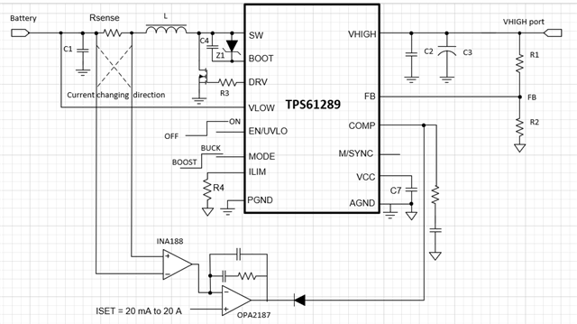
So, I found the TPS61289 which shows excellence data.

Requirement is:

  • Use one SuperCap as backup supply
    • Output Voltage: 5 V (normal operation mode), 4.5 V or also 5 V in backup mode
    • Output Current: Backup Mode: 500 mA (max), 250 mA (nom), Normal operation mode: 1 A
  • We are already using the TPS61094 for lower power requirements. But this will not work for the new requirments, at least not with one TPS61094.
    I have opened already another thread for this specific question Using TPS61094 in parallel mode, just for reference.

I have ordered already the evalboard TPS61289EVM and was now surprised, that I can't achive my goals on the board.
From all the parameters I see now, maybe this task is not achievable, but maybe I understand something wrong.

Will it be possible to use the TPS61289 for this scenario (backup power supply with charging function for SuperCap)?

  • I like to have a maximum charge voltage for the SuperCap of 2.7 V and a maximum charge Current of 300 mA (setable with some resistor or voltage divider)?
  • SuperCap should discharge as low as possible. VIN is stated as 0.5V in the datasheet (only in the head line...)

Manuall switch over between charging and discharging would be understood.

Thanks for your answer in advance,
Christian

  • Hi Christian,

    1. TPS61289 is designed to work with VHIGH higher than 3.4V and could be applied to this scenario.

    2. Could you tell me why TPS61289 cannot achieve your goal?

    3. 

    Manuall switch over between charging and discharging

    are you referring that change the charging and discharging mode manually?

    TPS61289 has a MODE pin to change the state.

    4. For your application, are you designed with const current charging or for voltage control?

    For const charging/discharging current, sense resistor could be placed on the supercap side and external amp can be used to regulate the comp.

    For voltage control, the device can use its comp.

    When discharging, VHIGH FB resistors are used to connect to FB pin to regulate the VHIGH like a normal Boost converter

    When charging, VLOW FB resistor are used to connect to FB pin to regulate the VLOW like a normal Buck converter.

    In voltage control mode, current can only be limited by its current limit pin setting.

    Could you elaborate your demand we can discuss more.

    Best Regards,

    Fergus

  • 1. That's understood, that TPS61289 is working for VHIGH > 3.4V. But if I wan't to use it with a SuperCap in a Boost Mode and it should operate below 1V on the low voltage side, how this should work?

    2. If you could simply tell me or much better give me a schematic (draft) how a circuitry could look with a single super cap and the given application parameters.
    3. Yes, it's clear, no question marks here.
    4. SuperCap Charging ist normally only done by constant current and limited by a voltage, typical 2.6..2.7V.

    What I really do not like, is to integrate a switch to control the FB voltage for boost and buck mode. Other regulators have there one dedicated FB for the low side. However, if this would be the only point, it would be worth to move forward with this solution.

    I still have no idea, how the comp control is working. There is no description at all in the datasheet. Just a black box to me.

    Thanks,
    Christian

  • Hi Christian,

    1. For TPS61289 or most boost, it will be hard to start at low voltage like 1V but after start, it can work with VLOW as low as 0.5V

    For device like TPS61299, it can start at 3.5V(Only with VLOW) or 3V(with VHIGH connected)

    2. please below block for capacitor discharge.

    After start up, the device can use a sense resistor to implement the const current control.

    When VHIGH reaches the target (programmed by R1,R2), the device enters voltage loop.

    For the capacitor charge, the FB need to connect to VLOW side, also, the current direction should be changed with the amp.

    3. For TPS61289 ,you could consider its comp to current as a voltage controlled current source.

    The comp can source current and thus can be clamped by external amp voltage.

    When working with voltage ,the diode is blocked and the device is regulated by its RC compensation loop.

    Best Regards,

    Fergus

  • Thanks again for coming back.

    The device doesn't need to startup at 0.5V. The backup solution should only switch over, once the main supply is shut down and should source further up to 3 minutes a connected device (with known power).

    Well, unfortunately you can't give me the solution I'm searching for.
    I need to create a non to complex solution for low cost. The TPS61094 solution is a perfect example for this.

    With TPS61289, it's becoming much more complex. And even before switching the feedback and so on, I would prefer a complete discrete solution with a Charger and Boost IC.

    I understand now more how the TPS61289 works. However, you should put much more information in the datasheet, it's to less in here. Or make a good application note.

    Thanks, not resolved (that's why I will not do the tick), but happy to exchange some theories.

    Christian

  • Hi Christian,

    Thank you for the advice.

    TPS61289 is original designed for BTS application and high current.

    Your idea to make an application note is good.

    Best Regards,

    Fergus