This thread has been locked.

If you have a related question, please click the "Ask a related question" button in the top right corner. The newly created question will be automatically linked to this question.

UCC29002: UCC29002: Query about the output of V+ and V-

Part Number: UCC29002


Tool/software:

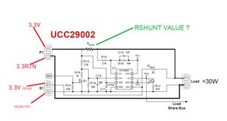
Hi Team, We are planning to use UCC29002 IC, and Input Voltage to V+ is 3.3V.

Can you please confirm the voltage for the Vdd?

The data sheet said in section 5.1:

Vdd Supply voltage, current-limited source  -0.3V to 15V

Vdd Supply voltage, low-impedance voltage source -0.3 to 13.5V

Also the data sheet said in section 5.3: 3 Recommended Operating Conditions

Vdd Supply voltage, low-impedance voltage source: 4.575V to 13.5V. Here it means UCC29002 is enabled when VDD is greater than 4.375 V.

Can Can you please confirm the voltage for the Vdd?

Regards,

Mateer Bhat

  • Hello Mateer, 

    Thank you for your interest in the UCC29002 load-share controller. 

    This device can allow accurate current sharing with your +3.3V modules.
    You are correct that bias voltage for each UCC29002 must be 4.375V < VDD < 15V.  This can come from a low-impedance "house-keeping" bias source between 4.375V and 13.5V, for example, or from a high-impedance source (basically having a series resistor to limit bias current) for any bias source > 13.5V.  
    Common voltages that may be available elsewhere in your system typically can be 5V, 9V, 12V, 20V, 24V, 48V, etc.  

    Note that the upper limit on the source voltage is not 15V.  That limit is the maximum voltage on the VDD pin of the UCC29002.  A series bias resistor is used to drop the voltage difference between the ~14.25V (+/- 0.75V) zener clamp inside the UCC29002 and any higher bias source that you might have available. 

    Please use the newly revised Excel design calculator tool to work out the design details: https://dr-download.ti.com/design-tools-simulation/calculation-tool/MD-GtQkXDHgDE/1.1/UCC29002_Design_Calculator.xlsx 

    Regards,
    Ulrich 

  • Hi Ulrich,

    Thanks for providing the valuable information.

    Here i am using two DC-DC converter module that provides me 3.3V output. DC-DC converter module 1 provide 3.3V and SENSE, same way the DC-DC converter module 2 provides 3.3V and SENSE.

    The system are not providing any other voltages.

    If I provide 3.3V to Vdd of the UCC29002, will the IC works and provide 3.3V output?

    Regards,

    Mateer Bhat 

  • Hi Mateer, 

    If you provide 3.3V to the UCC29002 VDD pin, the controller will not work and you will not be able to achieve current sharing with the other 3.3V module.
    You need to provide a separate bias source to VDD of UCC29002 that is > 4.375V. 
    Since no other voltages are available in your system, I suggest to design in a simple voltage-doubler or boost converter to generate ~6.6V to provide bias to the load-share controller.  You can have a single one to power both controllers or two separate ones, one for each controller. 
    Design for about 5mA loading for each load-share controller. (Actual bias current will be less than 5mA, but it is a good design target for margin.)  
    The doubler or boost circuit(s) can work open-loop; they do not need feedback or accurate regulation as long as Vbias does not fall below 4.1V at maximum loading. 

    Note: the UCC29002 does not "provide 3.3V output", or any output voltage. Your 3.3V module provides the 3.3V output.
    Each load-share controller simply measures the current from its corresponding module and compares it to the measurement from the other module's current.  
    The module with the lower current will have its feedback signal adjusted to slightly raise its output voltage (such as to 3.31V, for example) in order to raise its share of the total output current. 

    As the lower current increases, the higher current decreases.  When the two currents meet in the middle (that is, become nearly identical) the feedback adjustment stops and load-sharing is accomplished.  The load-share control loop bandwidth is designed to be much slower than the module's voltage loop bandwidth, so the current sharing adjustment is done slowly to avoid interfering with steady-state voltage regulation at each module.  

    Regards,
    Ulrich

  • Hi Ulrich,

    Thanks for providing the valuable information.

    Here i am using two DC-DC converter module that provides me 3.3V output. DC-DC converter module 1 provide 3.3V and SENSE, same way the DC-DC converter module 2 provides 3.3V and SENSE.

    Volatge Input =3.3V 

    Total load is 50W.

    What should be the resistor vlaue for RSHUNT?

  • Hello Mateer, 

    The answer to your question depends on making a few tradeoffs, so I can't answer it for you. 

    The Excel Calculator tool that I mentioned in my first reply will help you determine the best value to meet your requirements. 
    One concern is what is the maximum power loss that you can the shunt resistor to dissipate?
    Another is what is the maximum output current capability of each converter module? 
    I recommend that Rshunt be able to dissipate the power based on the maximum output current in case of an overload. 

    Another concern is how much Current-Sense Amplifier gain (Acsa) do you wish to design?  Lower values of Rshunt have low loss but require higher gain to achieve good current sharing.   High gain also amplifies noise and exaggerates the effects of input offsets.   Higher Rshunt requires less gain but increases loss.   I think gains > 300 might be a problem, but I'm no certain of it. 

    Please use the Excel tool to help make your design decisions.

    Regards,
    Ulrich 

  • Hi Ulrich,

    The  maximum output current capability of each converter module is 20A.

    Regards,

    Mateer Bhat

  • Hi Mateer, 

    Please use the Excel tool to help make your design decisions.
    I'm sorry I can't do the design work for you. 

    Regards,
    Ulrich

  • Hi Ulrich,

    Thanks for the support.

    I have a query related to RSHUNT. The  maximum output current capability of each converter module is 20A and the output load is 50W.

    I am assuming since the output load is 50W, the RSHUNT resistor should be able to take the load of 50W. Based on that assumption i have choosen

    500 mOhms ±5% 55W Chip Resistor PFC10  for the RSHUNT. The size of the resistor very much bigger than the UCC29002 IC. 

    Is my understanding correct? 

    Regards,

    Mateer Bhat

  • Hi Mateer, 

    There is a misunderstanding somewhere; I'm not sure where. 

    But consider it this way: 

    You have a 50W load at 3.3V = 15.2A to share by 2 power modules = 7.6A each when sharing. 
    For the sake of discussion, let's say you use a voltage doubler to bias the UCC29002, so VDD = 6.6V.
    Vcso(max) must be < VDD-1.7V for linearity, so Vcso(max) = 4.9V max. 

    Assuming the 3.3V module regulates to +/-1% which is +/-30mV, the shunt resistor will introduce a voltage drop that is usually compensated by the module's remote sense line.  To avoid needing too much compensation, propose 30mV for the shunt drop at 7.6A = 0.003947ohm, or 4mR for Rshunt. Steady-state power dissipation is 7.6*7.6*4mR = 0.231W.  But size the resistor to withstand 20A*20A*4mR = 1.6W in case of some kind of load fault or overload. 

    It you set Vcso(max) to 4.8V from 30mV of normal full-load sense signal = CSA gain of 4.8/.03 = 160. 
    Now you can consider that if you cut the current sense in half (2mR) you get half the dissipation, but need twice the CSA gain. Then noise and offsets become a larger factor in current sharing accuracy, as I mentioned in an earlier reply.    

    All design is making a series of tradeoffs between the benefits and disadvantages of doing one thing compared to doing another thing. 

    Regards,
    Ulrich