This thread has been locked.

If you have a related question, please click the "Ask a related question" button in the top right corner. The newly created question will be automatically linked to this question.

TPS22997: SOA limitations for TPS22997

Part Number: TPS22997


Tool/software:

Hello,

Using the evaluation board TPS22997EVM as a switch for my current source has destroyed the internal mosfet in TPS22997, the power switch turned into a series resistor of 3.8 Ohm’s. That happened as I changed the Ct (C4) capacitor to 10nF.

My question is: is there any SOA conditions for TPS22997 or power limitations which I have to comply with it? I cannot find anything in the datasheet.

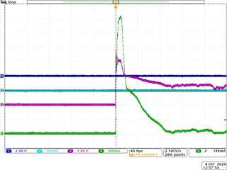
PS: My test setup: current source is based on LT3086 and the load is IR LED SFH4470S. I attached the screenshot for inrush current example where I connected the load by hand:

CH3: output

CH4: inrush current in the load


Thank you in advance.


Vitali Lach

  • Hello Vitali,

    Thanks for reaching to E2E.

    There could be abs max violation.

    Refer to 6.1 Absolute Maximum Ratings.

    Is there any way voltage going -ve on output or input?

    Thanks 

    Amrit 

  • Hello Amrit,

    thank you for your reply. My design does not exceed the Maximum Ratings, I’ve got 5V input voltage, no negative voltages available. Sinse TPS22997 has a NMOS inside, there could be in general a SOA (Safety Operation Area) limitations. The NMOS could be destroyed in linear mode if it’s operating outside the SOA. This is happened as I changed the Ct to 10nF causing some long timing for linear mode, so I suppose my design was outside SOA. For checking this I need the SOA/Power over time limitations from TI.

    Best Regards

    Vitali

  • Hello Vitali,

    I understand your concern but for integrated FET devices SOA is taken care already by internal control logic and charge pump mechanism.

    CT=10nF is something which is not tested for this device. you can check datasheet.

    How much turn-on time do you need for this?

    You can check eFuse solutions which has stronger charge pump.

    Thanks 

    Amrit 

  • Hello Amrit,

    thank you for that. There is no limitation regarding turn-on time for my design, I changed Ct to 10nF to reduce the inrush current. With 1nF, the inrush current was to high for my overcurrent monitoring. If I understand you correctly, I have to use the recommended values from the application section of datasheet? Maximum capacitive load of 220µF and up to 4700pF for Ct?

    Best Regards.

    V. Lach

  • Hello Vitali,

    Yes, please use the datasheet recommended values.

    Thanks 

    Amrit 

  • OK, thank you very much!

  • glad it helped

    ------------------------------------------------------------------------------------------------------------------------------

    Please click "This resolved my issue" button if this post answers your question.