Tool/software:
Hi,
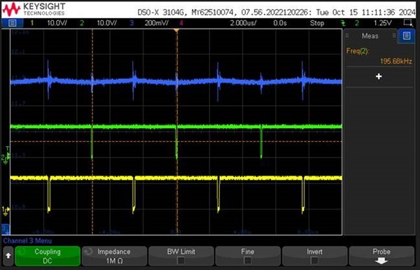
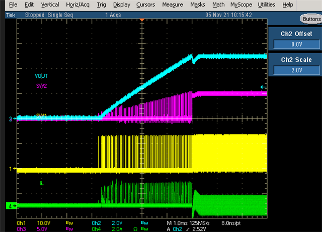
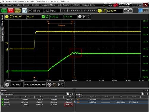
We are tesing TPS552892EVM found it have some unstable in power on, the peak ~13.46V,
Vout setting is EVM default = 12V. mode= FPWM, Iou= 0A.
May I know there have same behavior in your side?
Thanks!
Jeff
Tool/software:
Hi,
We are tesing TPS552892EVM found it have some unstable in power on, the peak ~13.46V,
Vout setting is EVM default = 12V. mode= FPWM, Iou= 0A.
May I know there have same behavior in your side?
Thanks!
Jeff