This thread has been locked.

If you have a related question, please click the "Ask a related question" button in the top right corner. The newly created question will be automatically linked to this question.

TPS7B7702-Q1: LDO UNSTABLE OUTPUT

Part Number: TPS7B7702-Q1

Tool/software:

Hi Team, 

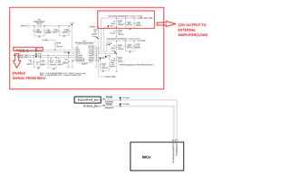
We have used tps7b7702qpwprq1 in our design to give power to an external amplifier.

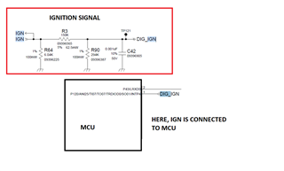
We have an external ignition signal to put the overall circuit into sleep and wake-up .

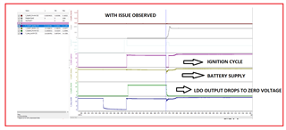
In few conditions, when ignition is removed and given back immediately, the LDO is working and we are getting desired output. However for the above same condition, we also observe that the LDO's output is Zero.

Is there any minimum timing required to be maintained for on and off cycle of the LDO ?

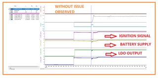
This is happening randomly for 5 out of 10 boards which is not acceptable and I have attached the waveforms for your reference.

  • Hi Sreeram,

    Could you please share a picture of your schematic? I am interested in seeing how the ignition input is provided and the nature of the load. It would be helpful if you can share the board layout as well. I have asked about any minimum timing required for this LDO to our systems engineer. I will add their response as soon as it's available.

    Best regards

    Ishaan

  • Hi Ishaan,

    Here, we are connecting audio amplifier as an external load which draws current around 60 mA.

    Also, I have attached the LDO and IGN circuit image for your reference.

    Here, IGN is an external input from the vehicle which will put the overall circuit into sleep and wake-up.

    Thanks,

    Sreeram R

  • Hi Sreeram,

    I see that for the failing boards, the 'Short to battery and reverse current detection' feature is kicking in. Please see section 7.3.3 of the device datasheet.

    Each time the LDO switch is enabled on the rising edge of the EN pin or during the exiting of the thermal shutdown, the short-to-battery detection occurs. At this moment, if the device detects the short-to-battery fault, the LDO switch is latched off.

    As per the input voltage profile on the failing boards, the Vout-Vin differential lies outside the range specified for this feature in the EC table of the datasheet (as shown below)

    The device is functioning as intended. As a suggestion, I would avoid having Vin - Vout go below 500 mV. You can have some minimum load to drain the output faster when ignition is removed and that should resolve the issue.

    Best Regards

    Ishaan

  • Hi Ishaan,

    Good day !

    The difference between output voltage and input voltage is within 500mV as the input voltage is 12 V.

    When we turn the ignition off and on, we can see that the short to battery condition gets occurs. However, it is occurring randomly in few boards.

    Also, it should be solved while turning the ignition back on correct . ( Toggling the ignition signal means toggling the enable signal)

    Should we toggle it multiple times to make it come back to normal state.

    Is there any timing requirements for it which we are not meeting which we asked earlier?

    Can we have a teams or webex meeting to discuss this issue in detail ?

    Thanks.

  • Hi Sreeram,

    From the scopeshot/ simulation window you provided above for the case in which the boards fail, you can see that Vin drops momentarily such Vout - Vin is within that -500mV to 110 mV range by the time ignition is toggled. This is not happening due to the device and needs to be investigated further at the board- level.

    Yes, the device should operate normally when the short-to-battery is removed and the EN pin is toggled. Could you please toggle the ignition signal again and re-check?

    There are no timing requirements to be maintained for on and off cycle of the LDO.

    Yes, we can definitely meet on Webex. My email is i-shetye@ti.com. I can also request a Systems engineer to join for more support.

    Best regards

    Ishaan

  • Hi Ishaan, 

    Can you suggest any software control solution for this ?

    Thanks,

    Sreeram R

  • HI Ishaan,

    Adding to that, the battery voltage gets dropped whenever ignition is pressed. If increasing the value of capacitance will reduce the voltage change due to crank ?

    Thanks,

    Sreeram R

  • HI Ishaan,

    I have a question after reviewing the waveform, where there is no issue in the LDO functionality also the battery seems to drop more than 110 mV, but the output  voltage doesn’t drop.

    Can you give your feedback on this below image ?

    Thanks,

    Sreeram R


  • Hi Sreeram,

    Are you asking about a way to control IGN digitally through software? You could have an architecture that clamps/ Boosts Vin OR discharges Vout soon after IGN is enabled. The exact specifics of such an architecture are outside my scope of knowledge and experience.

  • Are you talking about the input capacitance here? This is primarily to filter our small amplitude disturbances in VIN. Increasing input capacitor will not help in a cold crank/ Load dump. If Output capacitor is increased, Vout will not drain faster and the problem will persist.

  • Hi Sreeram,

    The maximum short-to battery threshold (Vout - Vin) is 110 mV. So you should look at the difference between the 2, which as per this image still lies in that range I shared above. Did you try toggling the IGN like I had suggested? Do you still want to discuss this over Webex?

  • HI Ishaan,

    Kindly find my queries below:

    • With respect to the input capacitance, I can see that in the datasheet, there is a recommendation to use 10 uF but here 4.7 uF capacitor is used in the design. So, if we use the recommended input capacitor, will it improve the battery line voltage.
    • I am attaching here two images where we have probed input battery line, ignition and output voltage where we observed two scenarios: with and without issue and we were able to see that in both the waveforms, there is drop in battery line when ignition is pressed but in one case it is working properly while in the other case the output voltage becomes zero.
    • Kindly refer the below images for your reference.

    WITH ISSUE SCOPESHOT:

    WITHOUT ISSUE SCOPESHOT:

    • Yes, we can definitely meet through teams or webex, kindly let me know the timings you will be comfortable with. I would like to add my system team also to this call.

    Thanks,

    Sreeram R

    • With respect to the input capacitance, I can see that in the datasheet, there is a recommendation to use 10 uF but here 4.7 uF capacitor is used in the design. So, if we use the recommended input capacitor, will it improve the battery line voltage. - Yes, this is possible. The input capacitor acts as an input filter for the LDO so it can smooth out disturbances on VIN caused by large impedances between supply and IN pin.
    • I am attaching here two images where we have probed input battery line, ignition and output voltage where we observed two scenarios: with and without issue and we were able to see that in both the waveforms, there is drop in battery line when ignition is pressed but in one case it is working properly while in the other case the output voltage becomes zero. - Is it possible to make cursor measurements for both cases between nominal Vin and minimum Vin (once Vin drops)
    • Kindly refer the below images for your reference.

    We will discuss further on our Webex meeting. I'll close the thread here.