This thread has been locked.

If you have a related question, please click the "Ask a related question" button in the top right corner. The newly created question will be automatically linked to this question.

TPS25750: non-PD adapter after first connection latched BQ25713 that no usb connection can charge

Part Number: TPS25750
Other Parts Discussed in Thread: BQ25713, , TPS25751

Tool/software:

Hi TI Team,

We are experiencing an issue with our custom board that uses TPS25750, BQ25713, and an EEPROM. This board has been in use for over a year, and we discovered the issue about a month ago. The board is equipped with 2S Li-ion batteries. When we plug in a non-PD adapter, the BQ25713 charges the battery, but when we unplug this adapter, the BQ25713 appears to latch, and neither non-PD nor PD adapters are able to charge the batteries afterward.

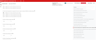
We do not have the D+ and D- lines connected, as we do not want to use an external switch for data connection. Because of this, we set the first PDO to 5V @ 500mA, as defined in the following JSON configuration:

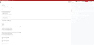
{"questionnaire":{"version":"7.0.3.13","answers":[6,null,1,null,0,null,1,null,1,null,1,8.352,2.048,null,null],"options":{},"configID":"0000","vendorID":"0000"},"configuration":{"data":{"selected_ace":[{"register":6,"data":[0,0,0,0,0,0,0,0]},{"register":22,"data":[10,48,48,77,0,0,0,0,0,0,3]},{"register":50,"data":[0,168,42,44,145,1,38,44,209,2,0,44,177,4,0,44,65,6,0,0,0,0,0,0,0,0,0,0,0,0,0]},{"register":51,"data":[3,50,144,1,0,44,209,34,0,44,177,4,0,244,65,6,0,69,65,6,0,0,0,0,0,0,0,0,0]},{"register":92,"data":[0,0,0,0,0,0,0,0,0,16,0,0,0,0,0,0,0,0,0,0,8,0,0,0,0,12,0,0,0,0,0,0,0,0,0,0,0,0,0,0,0,0,0,0,0,0,0,0,0]},{"register":117,"data":[0,0,0,0]}]}}}

The issue resolves when we disconnect either the battery or the USB (by "resolve" I mean that charging via a USB-PD adapter becomes possible again).

It seems like a hard reset helps, so we tried to disable the VIN_3V3 rail and re-enable it when a USB is plugged in or when the device is on, but this approach did not work. Additionally, we noticed that the board consumes twice the current in standby mode.

The OTG/VAP pin is pulled down. ILIM_HIZ is set to 2.1V (2800mA). CELL_BATPRESZ is set to 2.3V (the pull-up is located near the battery; when the battery is disconnected, the pull-up is also disconnected), which is approximately 40% of VDDA for a 2S configuration.

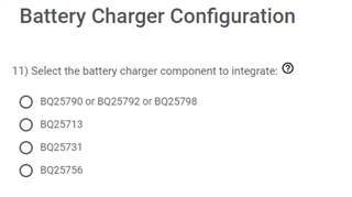
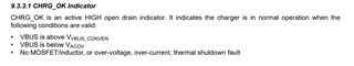
We need to understand why the BQ25713 latches when we connect the board to a PC.

We also have a question: we are considering using TPS25751 as it appears to be pin-compatible, but we cannot export the JSON configuration or binary for this device.

Any insights or suggestions would be greatly appreciated.

Best Regards, 
Rafał 

  • Hi Rafal, 

    Thank you for reaching out!

    I am looking into this and will provide feedback by end of week. 

    Best Regards, 

    Aya Khedr 

  • Hi Rafal, 

    We are recommending the TPS25751 for all new designs. It is pin-to-pin compatible and has improved I2C control for battery chargers such as the BQ25713 Please see the following FAQ for more information.

    You should be able to export json and binary using the Application Customization Tool after answering all questions on the first page. Also, please see the TPS25751 EVM User's Guide section 3.2 Software Development.

    Best Regards, 

    Aya Khedr 

  • I tried to export JSON and binary files for TPS25751, from the tool, but it appears to be blocked.

  • Hi Rafal, 

    It looks like you did not select a battery charger in question #11. Please make sure to answer all questions, the GUI should then allow you to export settings.  

    Also, please generate a new json for the TPS25751, you should not import settings from the TPS25750. 

    Best Regards, 

    Aya Khedr 

  • Still not working. i have clickout all  possible queastions, in basic mode, and I tried even in advance mode 

  • Hi Rafal, 

    From the screenshot above, it appears questions 9 and 10 are unanswered. 

    Best Regards, 

    Aya Khedr

  • Hi Aya
    Thank you :) 

    Best Regards, 
    Rafał 

  • I bought the new version of the TPS25751S and soldered it in place of the old one (TPS25750S). I programmed a new EEPROM binary and then checked if it was working properly.

    Unfortunately, it's not. I connected the battery, plugged in the PD adapter, but it's still not functioning. The CC transaction seems correct, as the voltage is properly set to 9V or 15V, depending on the adapter.

    However, for some reason, the power path isn't switching.

    I have tried many configurations of the EEPROM binary, and I have I2C logs for the simplest configuration.


    {
      "questionnaire": {
        "device": "TPS25751",
        "answers": [
          null,
          6,
          4,
          2,
          1,
          0,
          3,
          0,
          1,
          1,
          1,
          1,
          1,
          0,
          8.352,
          2.496,
          0,
          0,
          0
        ],
        "vendorId": "0000",
        "productId": "0000",
        "version": "1.0.0.2"
      }
    }


    Eneter command: 
    int?
    Data  Interrupt Event for I2C1 Register: (b'\x00\x00\x00\x00\x00\x00\x00\x00\x00\x00\x00', 11)
    Decode Interrupt Event for I2C1 Register:
    Eneter command:: 
    showbytes
    Eneter command:: 
    read_status
    Status:
     - Plug Present: 0
     - Connection State: No connection
     - Plug Orientation: Upside-Up
     - Port Role: Sink
     - Data Role: UFP (Device)
     - VBUS Status: At vSafe0V (less than 0.8V)
     - USB Host Present: No host present
     - Acting as Legacy: Not in legacy mode
    PD Status:
     - Hard Reset Reason: No hard reset
     - Soft Reset Reason: No soft reset
     - Present PD Role: Sink
     - CC Pullup Value: No CC pull-down
    Byte 0: 0x0     B0-B7   B0(0):  0,      B1(1):  0,      B2(2):  0,      B3(3):  0,      B4(4):  0,      B5(5):  0,      B6(6):  0,      B7(7):  0,
    Byte 1: 0x0     B8-B15  B8(0):  0,      B9(1):  0,      B10(2):  0,     B11(3):  0,     B12(4):  0,     B13(5):  0,     B14(6):  0,     B15(7):  0,
    Byte 2: 0x0     B16-B23 B16(0):  0,     B17(1):  0,     B18(2):  0,     B19(3):  0,     B20(4):  0,     B21(5):  0,     B22(6):  0,     B23(7):  0,
    Byte 3: 0x0     B24-B31 B24(0):  0,     B25(1):  0,     B26(2):  0,     B27(3):  0,     B28(4):  0,     B29(5):  0,     B30(6):  0,     B31(7):  0,
    Byte 4: 0x40    B32-B39 B32(0):  0,     B33(1):  0,     B34(2):  0,     B35(3):  0,     B36(4):  0,     B37(5):  0,     B38(6):  1,     B39(7):  0,
    Power Path Status:
     - PP1 Switch State: Disabled
     - PP3 Switch State: Disabled
     - PP1 Overcurrent: No
     - PPCable1 Overcurrent: No
     - Power Source: Powered from VIN_3V3
    Byte 0: 0x0     B0-B7   B0(0):  0,      B1(1):  0,      B2(2):  0,      B3(3):  0,      B4(4):  0,      B5(5):  0,      B6(6):  0,      B7(7):  0,
    Byte 1: 0x0     B8-B15  B8(0):  0,      B9(1):  0,      B10(2):  0,     B11(3):  0,     B12(4):  0,     B13(5):  0,     B14(6):  0,     B15(7):  0,
    Power Status:
     - Power Connection: No connection
     - Present PD Role: Sink
     - Type-C Current: USB Default Current
     - Charger Detect Status: No detection
     - Charger Advertise Status: Charger advertise disabled or not run
    Eneter command:
    int?
    Byte 0: 0x0     B0-B7   B0(0):  0,      B1(1):  0,      B2(2):  0,      B3(3):  0,      B4(4):  0,      B5(5):  0,      B6(6):  0,      B7(7):  0,
    Byte 1: 0x0     B8-B15  B8(0):  0,      B9(1):  0,      B10(2):  0,     B11(3):  0,     B12(4):  0,     B13(5):  0,     B14(6):  0,     B15(7):  0,
    Byte 2: 0x0     B16-B23 B16(0):  0,     B17(1):  0,     B18(2):  0,     B19(3):  0,     B20(4):  0,     B21(5):  0,     B22(6):  0,     B23(7):  0,
    Byte 3: 0x0     B24-B31 B24(0):  0,     B25(1):  0,     B26(2):  0,     B27(3):  0,     B28(4):  0,     B29(5):  0,     B30(6):  0,     B31(7):  0,
    Byte 4: 0x0     B32-B39 B32(0):  0,     B33(1):  0,     B34(2):  0,     B35(3):  0,     B36(4):  0,     B37(5):  0,     B38(6):  0,     B39(7):  0,
    Byte 5: 0x0     B40-B47 B40(0):  0,     B41(1):  0,     B42(2):  0,     B43(3):  0,     B44(4):  0,     B45(5):  0,     B46(6):  0,     B47(7):  0,
    Byte 6: 0x0     B48-B55 B48(0):  0,     B49(1):  0,     B50(2):  0,     B51(3):  0,     B52(4):  0,     B53(5):  0,     B54(6):  0,     B55(7):  0,
    Byte 7: 0x0     B56-B63 B56(0):  0,     B57(1):  0,     B58(2):  0,     B59(3):  0,     B60(4):  0,     B61(5):  0,     B62(6):  0,     B63(7):  0,
    Byte 8: 0x0     B64-B71 B64(0):  0,     B65(1):  0,     B66(2):  0,     B67(3):  0,     B68(4):  0,     B69(5):  0,     B70(6):  0,     B71(7):  0,
    Byte 9: 0x0     B72-B79 B72(0):  0,     B73(1):  0,     B74(2):  0,     B75(3):  0,     B76(4):  0,     B77(5):  0,     B78(6):  0,     B79(7):  0,
    Byte 10: 0x0    B80-B87 B80(0):  0,     B81(1):  0,     B82(2):  0,     B83(3):  0,     B84(4):  0,     B85(5):  0,     B86(6):  0,     B87(7):  0,
    Dane z Interrupt Event for I2C1 Register: (b'\x00\x00\x00\x00\x00\x00\x00\x00\x00\x00\x00', 11)
    Dekodowanie Interrupt Event for I2C1 Register:
    Eneter command: 
    mode?
    READ MODE :
    Byte 0: 0x41    B0-B7   B0(0):  1,      B1(1):  0,      B2(2):  0,      B3(3):  0,      B4(4):  0,      B5(5):  0,      B6(6):  1,      B7(7):  0,
    Byte 1: 0x50    B8-B15  B8(0):  0,      B9(1):  0,      B10(2):  0,     B11(3):  0,     B12(4):  1,     B13(5):  0,     B14(6):  1,     B15(7):  0,
    Byte 2: 0x50    B16-B23 B16(0):  0,     B17(1):  0,     B18(2):  0,     B19(3):  0,     B20(4):  1,     B21(5):  0,     B22(6):  1,     B23(7):  0,
    Byte 3: 0x20    B24-B31 B24(0):  0,     B25(1):  0,     B26(2):  0,     B27(3):  0,     B28(4):  0,     B29(5):  1,     B30(6):  0,     B31(7):  0,
    (b'APP ', 4)
    Eneter command:
    int?
    Byte 0: 0x0     B0-B7   B0(0):  0,      B1(1):  0,      B2(2):  0,      B3(3):  0,      B4(4):  0,      B5(5):  0,      B6(6):  0,      B7(7):  0,
    Byte 1: 0x0     B8-B15  B8(0):  0,      B9(1):  0,      B10(2):  0,     B11(3):  0,     B12(4):  0,     B13(5):  0,     B14(6):  0,     B15(7):  0,
    Byte 2: 0x0     B16-B23 B16(0):  0,     B17(1):  0,     B18(2):  0,     B19(3):  0,     B20(4):  0,     B21(5):  0,     B22(6):  0,     B23(7):  0,
    Byte 3: 0x0     B24-B31 B24(0):  0,     B25(1):  0,     B26(2):  0,     B27(3):  0,     B28(4):  0,     B29(5):  0,     B30(6):  0,     B31(7):  0,
    Byte 4: 0x0     B32-B39 B32(0):  0,     B33(1):  0,     B34(2):  0,     B35(3):  0,     B36(4):  0,     B37(5):  0,     B38(6):  0,     B39(7):  0,
    Byte 5: 0x0     B40-B47 B40(0):  0,     B41(1):  0,     B42(2):  0,     B43(3):  0,     B44(4):  0,     B45(5):  0,     B46(6):  0,     B47(7):  0,
    Byte 6: 0x0     B48-B55 B48(0):  0,     B49(1):  0,     B50(2):  0,     B51(3):  0,     B52(4):  0,     B53(5):  0,     B54(6):  0,     B55(7):  0,
    Byte 7: 0x0     B56-B63 B56(0):  0,     B57(1):  0,     B58(2):  0,     B59(3):  0,     B60(4):  0,     B61(5):  0,     B62(6):  0,     B63(7):  0,
    Byte 8: 0x0     B64-B71 B64(0):  0,     B65(1):  0,     B66(2):  0,     B67(3):  0,     B68(4):  0,     B69(5):  0,     B70(6):  0,     B71(7):  0,
    Byte 9: 0x0     B72-B79 B72(0):  0,     B73(1):  0,     B74(2):  0,     B75(3):  0,     B76(4):  0,     B77(5):  0,     B78(6):  0,     B79(7):  0,
    Byte 10: 0x0    B80-B87 B80(0):  0,     B81(1):  0,     B82(2):  0,     B83(3):  0,     B84(4):  0,     B85(5):  0,     B86(6):  0,     B87(7):  0,
    Data z Interrupt Event for I2C1 Register: (b'\x00\x00\x00\x00\x00\x00\x00\x00\x00\x00\x00', 11)
    Decode Interrupt Event for I2C1 Register:
    Eneter command:
    int?
    Byte 0: 0x8     B0-B7   B0(0):  0,      B1(1):  0,      B2(2):  0,      B3(3):  1,      B4(4):  0,      B5(5):  0,      B6(6):  0,      B7(7):  0,
    Byte 1: 0x10    B8-B15  B8(0):  0,      B9(1):  0,      B10(2):  0,     B11(3):  0,     B12(4):  1,     B13(5):  0,     B14(6):  0,     B15(7):  0,
    Byte 2: 0x0     B16-B23 B16(0):  0,     B17(1):  0,     B18(2):  0,     B19(3):  0,     B20(4):  0,     B21(5):  0,     B22(6):  0,     B23(7):  0,
    Byte 3: 0x5     B24-B31 B24(0):  1,     B25(1):  0,     B26(2):  1,     B27(3):  0,     B28(4):  0,     B29(5):  0,     B30(6):  0,     B31(7):  0,
    Byte 4: 0x0     B32-B39 B32(0):  0,     B33(1):  0,     B34(2):  0,     B35(3):  0,     B36(4):  0,     B37(5):  0,     B38(6):  0,     B39(7):  0,
    Byte 5: 0x8     B40-B47 B40(0):  0,     B41(1):  0,     B42(2):  0,     B43(3):  1,     B44(4):  0,     B45(5):  0,     B46(6):  0,     B47(7):  0,
    Byte 6: 0x0     B48-B55 B48(0):  0,     B49(1):  0,     B50(2):  0,     B51(3):  0,     B52(4):  0,     B53(5):  0,     B54(6):  0,     B55(7):  0,
    Byte 7: 0x1     B56-B63 B56(0):  1,     B57(1):  0,     B58(2):  0,     B59(3):  0,     B60(4):  0,     B61(5):  0,     B62(6):  0,     B63(7):  0,
    Byte 8: 0x0     B64-B71 B64(0):  0,     B65(1):  0,     B66(2):  0,     B67(3):  0,     B68(4):  0,     B69(5):  0,     B70(6):  0,     B71(7):  0,
    Byte 9: 0x0     B72-B79 B72(0):  0,     B73(1):  0,     B74(2):  0,     B75(3):  0,     B76(4):  0,     B77(5):  0,     B78(6):  0,     B79(7):  0,
    Byte 10: 0x0    B80-B87 B80(0):  0,     B81(1):  0,     B82(2):  0,     B83(3):  0,     B84(4):  0,     B85(5):  0,     B86(6):  0,     B87(7):  0,
    Data Interrupt Event for I2C1 Register: (b'\x08\x10\x00\x05\x00\x08\x00\x01\x00\x00\x00', 11)
    Decode Interrupt Event for I2C1 Register:
    1 - Bit 3: Plug Insert or Remove
    1 - Bit 24: Power Status Updated
    1 - Bit 43: Plug Early Notification - Wykryto po��aczenie, ale nie zosta��o ono zdebouncowane
    Eneter command: 
    read_status
    Status:
     - Plug Present: 1
     - Connection State: Connection present no Ra detected
     - Plug Orientation: Upside-Up
     - Port Role: Sink
     - Data Role: UFP (Device)
     - VBUS Status: Within expected limits
     - USB Host Present: Attached source is not data capable
     - Acting as Legacy: Not in legacy mode
    PD Status:
     - Hard Reset Reason: No hard reset
     - Soft Reset Reason: No soft reset
     - Present PD Role: Sink
     - CC Pullup Value: 3.0A (SinkTxOK)
    Byte 0: 0x0     B0-B7   B0(0):  0,      B1(1):  0,      B2(2):  0,      B3(3):  0,      B4(4):  0,      B5(5):  0,      B6(6):  0,      B7(7):  0,
    Byte 1: 0x0     B8-B15  B8(0):  0,      B9(1):  0,      B10(2):  0,     B11(3):  0,     B12(4):  0,     B13(5):  0,     B14(6):  0,     B15(7):  0,
    Byte 2: 0x0     B16-B23 B16(0):  0,     B17(1):  0,     B18(2):  0,     B19(3):  0,     B20(4):  0,     B21(5):  0,     B22(6):  0,     B23(7):  0,
    Byte 3: 0x0     B24-B31 B24(0):  0,     B25(1):  0,     B26(2):  0,     B27(3):  0,     B28(4):  0,     B29(5):  0,     B30(6):  0,     B31(7):  0,
    Byte 4: 0x40    B32-B39 B32(0):  0,     B33(1):  0,     B34(2):  0,     B35(3):  0,     B36(4):  0,     B37(5):  0,     B38(6):  1,     B39(7):  0,
    Power Path Status:
     - PP1 Switch State: Disabled
     - PP3 Switch State: Disabled
     - PP1 Overcurrent: No
     - PPCable1 Overcurrent: No
     - Power Source: Powered from VIN_3V3
    Byte 0: 0xf     B0-B7   B0(0):  1,      B1(1):  1,      B2(2):  1,      B3(3):  1,      B4(4):  0,      B5(5):  0,      B6(6):  0,      B7(7):  0,
    Byte 1: 0x2     B8-B15  B8(0):  0,      B9(1):  1,      B10(2):  0,     B11(3):  0,     B12(4):  0,     B13(5):  0,     B14(6):  0,     B15(7):  0,
    Power Status:
     - Power Connection: Connection present
     - Present PD Role: Source
     - Type-C Current: Explicit PD contract sets current
     - Charger Detect Status: No detection
     - Charger Advertise Status: Charger advertisement complete
    Eneter command:

    commands: 

    • bqread - it is function to read BQ25713 via TPS data1 & cmd1  and its firts command to show if it works properly 
    • int? - it ask TPS for Interrupt Event  ( register 0x14 )
    • int r - reset  Interrupt Event  ( send to 0x18  [0xFF for _ in range(11)] )
    • read_status - get TPS status, PD status, Power Path status  and Power status 

    Best Regards, 
    Rafał 

  • Hi Rafal, 

    Based on the status reads provided, I can see that the PD controller is negotiating a contract successfully, which means that the sinking power path is enabled. Could you try reading the power path status register again? 

    Can you confirm that the BQ is responding? Do you have I2C logs?

    Best Regards, 

    Aya Khedr 

  • Hi Aya,

    To answer your question, yes, the BQ is responding—whether there's no adapter, a PD adapter, or a non-PD adapter connected, even when I short the power switch from the TPS.

    Here are the details from the bqread command:

    bqread
    Register Offest (hex, np. 0x00): 0x2f
    How many bytes you want to read? (max 14): 1
    Byte 0: 0x88    B0-B7   B0(0):  0,      B1(1):  0,      B2(2):  0,      B3(3):  1,      B4(4):  0,      B5(5):  0,      B6(6):  0,      B7(7):  1,
    Enter command : 
    int?
    Interrupt Event for I2C1
    Byte 0: 0x8     B0-B7   B0(0):  0,      B1(1):  0,      B2(2):  0,      B3(3):  1,      B4(4):  0,      B5(5):  0,      B6(6):  0,      B7(7):  0,
    Byte 1: 0x50    B8-B15  B8(0):  0,      B9(1):  0,      B10(2):  0,     B11(3):  0,     B12(4):  1,     B13(5):  0,     B14(6):  1,     B15(7):  0,
    Byte 2: 0xa0    B16-B23 B16(0):  0,     B17(1):  0,     B18(2):  0,     B19(3):  0,     B20(4):  0,     B21(5):  1,     B22(6):  0,     B23(7):  1,
    Byte 3: 0x45    B24-B31 B24(0):  1,     B25(1):  0,     B26(2):  1,     B27(3):  0,     B28(4):  0,     B29(5):  0,     B30(6):  1,     B31(7):  0,
    Byte 4: 0x0     B32-B39 B32(0):  0,     B33(1):  0,     B34(2):  0,     B35(3):  0,     B36(4):  0,     B37(5):  0,     B38(6):  0,     B39(7):  0,
    Byte 5: 0x8     B40-B47 B40(0):  0,     B41(1):  0,     B42(2):  0,     B43(3):  1,     B44(4):  0,     B45(5):  0,     B46(6):  0,     B47(7):  0,
    Byte 6: 0x0     B48-B55 B48(0):  0,     B49(1):  0,     B50(2):  0,     B51(3):  0,     B52(4):  0,     B53(5):  0,     B54(6):  0,     B55(7):  0,
    Byte 7: 0x1     B56-B63 B56(0):  1,     B57(1):  0,     B58(2):  0,     B59(3):  0,     B60(4):  0,     B61(5):  0,     B62(6):  0,     B63(7):  0,
    Byte 8: 0x0     B64-B71 B64(0):  0,     B65(1):  0,     B66(2):  0,     B67(3):  0,     B68(4):  0,     B69(5):  0,     B70(6):  0,     B71(7):  0,
    Byte 9: 0x0     B72-B79 B72(0):  0,     B73(1):  0,     B74(2):  0,     B75(3):  0,     B76(4):  0,     B77(5):  0,     B78(6):  0,     B79(7):  0,
    Byte 10: 0x1    B80-B87 B80(0):  1,     B81(1):  0,     B82(2):  0,     B83(3):  0,     B84(4):  0,     B85(5):  0,     B86(6):  0,     B87(7):  0,
    Data from  Interrupt Event for I2C1 Register: (b'\x08P\xa0E\x00\x08\x00\x01\x00\x00\x01', 11)
    Decode  Interrupt Event for I2C1 Register:
    1 - Bit 3: Plug Insert or Remove
    1 - Bit 24: Power Status Updated
    1 - Bit 30: CMD1 Complete
    1 - Bit 43: Plug Early Notification - Wykryto po��aczenie, ale nie zosta��o ono zdebouncowane
    1 - Bit 80: Patch Loaded - Pakiet zosta�� za��adowany do urzadzenia
    Eneter command : 
    pwr?
    Power Path Status:
    Byte 0: 0x0     B0-B7   B0(0):  0,      B1(1):  0,      B2(2):  0,      B3(3):  0,      B4(4):  0,      B5(5):  0,      B6(6):  0,      B7(7):  0,
    Byte 1: 0x0     B8-B15  B8(0):  0,      B9(1):  0,      B10(2):  0,     B11(3):  0,     B12(4):  0,     B13(5):  0,     B14(6):  0,     B15(7):  0,
    Byte 2: 0x0     B16-B23 B16(0):  0,     B17(1):  0,     B18(2):  0,     B19(3):  0,     B20(4):  0,     B21(5):  0,     B22(6):  0,     B23(7):  0,
    Byte 3: 0x0     B24-B31 B24(0):  0,     B25(1):  0,     B26(2):  0,     B27(3):  0,     B28(4):  0,     B29(5):  0,     B30(6):  0,     B31(7):  0,
    Byte 4: 0x40    B32-B39 B32(0):  0,     B33(1):  0,     B34(2):  0,     B35(3):  0,     B36(4):  0,     B37(5):  0,     B38(6):  1,     B39(7):  0,
    Decoded Power Path Status:
     - PP1 Switch State: Disabled
     - PP3 Switch State: Disabled
     - PP1 Overcurrent: No
     - PPCable1 Overcurrent: No
     - Power Source: Powered from VIN_3V3
    Power Status :
    Byte 0: 0xf     B0-B7   B0(0):  1,      B1(1):  1,      B2(2):  1,      B3(3):  1,      B4(4):  0,      B5(5):  0,      B6(6):  0,      B7(7):  0,
    Byte 1: 0x2     B8-B15  B8(0):  0,      B9(1):  1,      B10(2):  0,     B11(3):  0,     B12(4):  0,     B13(5):  0,     B14(6):  0,     B15(7):  0,
    Decoded Power Status:
     - Power Connection: Connection present
     - Present PD Role: Source
     - Type-C Current: Explicit PD contract sets current
     - Charger Detect Status: No detection
     - Charger Advertise Status: Charger advertisement complete

    I also checked with the int? command, showing the Interrupt Event for I2C1.

    It seems that the power path status hasn't updated for some reason.

  • Hi Rafal, 

    I will look into this further and get back to you with feedback Wednesday.

    Best Regards, 

    Aya Khedr

  • Hi Rafal, 

    It seems there is a GUI bug that is disabling the power path. We are working on releasing a new GUI with this bug resolved (later this week or early next week).

    In the meantime, here is a binary file, based off of your json, that you could use for testing. To flash from binary file, go to "Flash Top Device" --> "Flash to device from binary file"

    https://e2e.ti.com/cfs-file/__key/communityserver-discussions-components-files/196/Rafal_5F00_Config.bin

    Best Regards, 

    Aya Khedr

  • Hi Aya, 
    Thank you for this bin file. I have tested it and it works.
    There is also one bug that pin charge ok from BQ25713 do not work.

    Best Regards, 

    Rafał 

  • Hi Rafal, 

    Glad to hear its working.

    Please verify that the following conditions are valid for CHRG_OK pin. For further questions, please post a new thread with "BQ25713" as the part number and  BQ expert will assist you. 

    Best Regards, 

    Aya Khedr