This thread has been locked.

If you have a related question, please click the "Ask a related question" button in the top right corner. The newly created question will be automatically linked to this question.

TPS65988: Issue with PS_Swap to SRC

Part Number: TPS65988
Other Parts Discussed in Thread: TPS65987D

Tool/software:

TPS65988 PS_Swap problem

Summary

In this design we connect a USB-C charger to the 65988 Port2 USB-C port and an iPad to the Port1 USB-C.  It is our goal that the iPad charges while plugged into Port1.  This requires that Port1 on the 65988 be a UFP with its power role set to SOURCE.  In the failing case, the iPad connects but the 65988 never properly switches to SOURCE mode.


Details

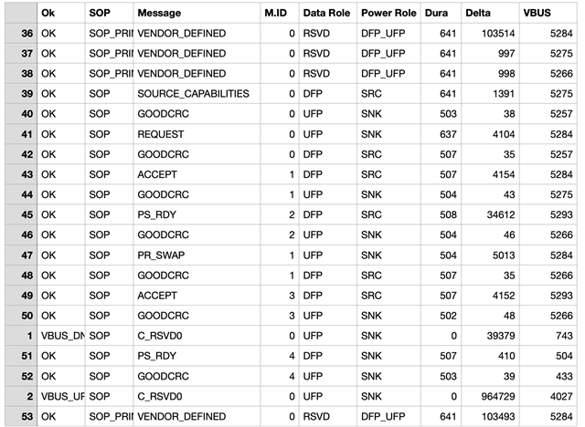
The charger is plugged into port 2.  Port1 is configured for as a UFP and the configuration lists “prefer SOURCE” and the bits for Initiate and Process PS_Swap.  The PS_Swap process starts Ok, but fails to complete and the system cycles continuously with VBUS turning on and off.  Consider this PD trace:

The iPad connects at the top and with its SOURCE_CAPABILITIES message 39 as DFP and SOURCE.  Later the 65988 issues the PS_SWAP at message 47 (as UFP SNK).  The iPad accepts in 49 and in 51 and it issues a PS_RDY indicating the the iPad has changed to SNK.  However, the problem seems to be that the 65988 never issues its PS_RDP indicating that it has switched to SRC.  The cycle continues and this pattern repeats over and over.

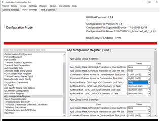
Configuration of 65988

A Windbond W25Q80DV serial flash chip provides configuration to the 65988
Port 1 (for the iPad) is set in the UI to UFP and the power role “prefers SOURCE”
Port 1 Control register bits “Initiate” and “Process” Swap to Source are both set
PP_EXT1 (PP3) is configured as an output and the 65988 turns this on (to supply VBUS to Port 1) during the above PD exchange
A Fixed Tx Source PDO for 5V @ 3A is setup for Port 1Here is a system block diagram:


  • Hi Erich,

    In order for the TPS65987D to send the PS_RDY message during the PR_SWAP to source, it needs to be able to provide 5-V. A new PD contract always starts as a 5-V Default type-C contract.

    There could be a couple system and pjt configuration related issues.

    First, check your "PP X Switch Config" Fields in "Global System Config" to make sure that the correct power path is configured as a Source (in this case, likely PP 1).

    Next, when the PR_SWAP occurs, make sure 5-V is provided to the PPHV/VSYS side of the PD controller.

    The TPS65988 ports operate independently of each other in regards to the USB-C PD negotiation on each port. You need to make sure that the DC-DC feeding the source port of the PD controller knows when to transition between different voltages to support correct source operation. Typically we use GPIOs (See the EVM PDO GPIOs).

    Thanks and Regards,

    Chris

  • Chris,

    Thanks for the suggestions.  We found a bug in the power switch circuit for this revision of the hardware.  

    Now we have encountered another problem.  Now, the PR_Swap works correctly and the iPad switches to DFP/Sink and our side turns on VBUS.  However, our SOURCE_CAPABILITIES message is for 5000 mV @ 900 mA instead of the 5v @ 3A that's in the Tx Source register.  The value 900 seems suggestive, but we don't understand what it is used here.

    Any thoughts as to why this is?

  • Hi Eric,

    There could be a couple things here:

    1. Make sure you are on the right port. There are different source capabilities for each port, and each will advertise differently
    2. Dead battery
      1. When the TPS65988 boots in dead battery(powered from the Type-C connector instead of VIN3V3 pin), it will assert a dead battery flag internally that changes behavior. It prevents both ports from sourcing more than 5V and it does appear to lock the current at 900mA.
      2. The intention of this feature is to limit power drawn if there is no dedicate power other than the USB-C Sink, you will need to either find a way to clear the flag, or to prevent entry with the flag
      3. To check the flag, see the "PowerSource" bits in the "Power Path Status" register
      4. To clear the flag, you can use:
        1. the "DBfg" 4CC command
        2. the "Barrel_Jack_Event" GPIO event
          1. This one does have additional behavior, so check the TRM gpio events
        3. Consider following parts of this App note to create a loadable configuration. The configuration can be empty (don't change any registers), but configure the App Config register to trigger a "DBfg" command when a GPIO is asserted.
          1.  
          2.  
      5. To prevent entry, the PD controller needs to power up from VIN3V3. If you only power from VBUS, you will need to clear the flag

    Thanks and Regards,

    Chris

  • Thanks Chris for the suggestion to look at the DeadBattery flag.  I had code in the uC firmware to address this but it wasn't being called.  We now have Port 1 VBUS = 5v @ 3A.

  • Good to hear!

    Closing this thread now. If you have a continuation of this question, feel free to open this thread. Otherwise you can open a new thread with a new topic.

    Thanks and Regards,

    Chris