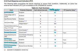
Other Parts Discussed in Thread: BQ25798, BQ25798EVM
Tool/software:
We are considering a configuration in which the TPS25947EVM is placed in front of the input of the BQ25798EVM in order to control whether the power input from the host MCU to the BQ25798 is permitted or prohibited.
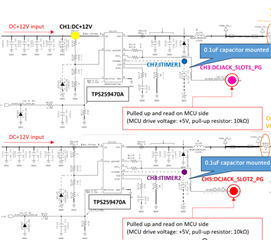
Specifically, the BQ25798EVM is assembled in the configuration shown in Figure 9-2, Single Input Connected to VBUS Directly Without ACFET-RBFET, on page 31 of the datasheet, and an eFuse (TPS259470A ) is placed on the VIN1 input side of the BQ25798EVM.
However, the FLTb pin of the TPS259470A is falling after power input, and we are having difficulty finding the cause.
Note that the input power source is not in an overvoltage/constant voltage/overcurrent state.
Also, disconnecting the VBUS line of the BQ25798 and the VOUT of the TPS25947EVM will stop this phenomenon from occurring.
Any ideas as to why FLTb falls off after power input?
<Configuration of the actual machine>
TPS25947EVM:
- OVLO voltage: 15.38V detection, 13.97V return
- OVLO voltage: 15.38V detected, 13.97V released
- ILIM resistor: 3kΩ (input current limited at 1.11A)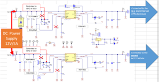
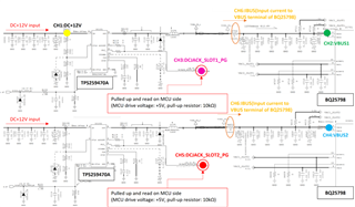
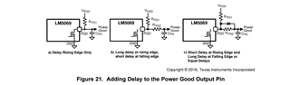
<Block Diagram>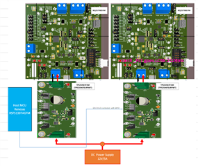
<Current problems>
- The _FLT pin drops momentarily after power is input.
- Input power is below the OVLO/UVLO/ILIM threshold.
- The problem is solved by disconnecting the VBUS line (VIN1 pin) of BQ25798EVM and the VOUT pin of TPS25947EVM.
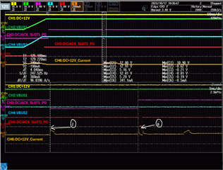
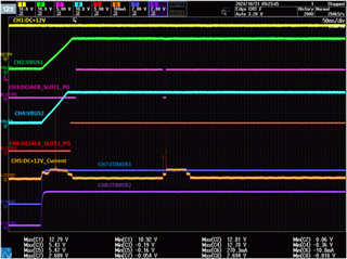
<Measurement waveform>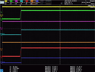
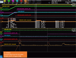
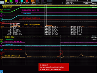
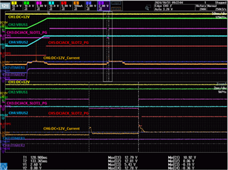
<Expanded figure of measured waveform>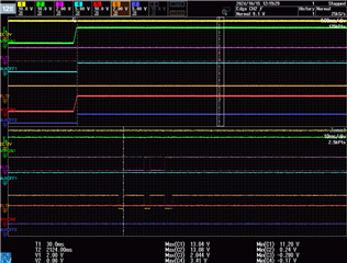
I have the same question about BQ25798.
Please see the end of the thread below.
https://e2e.ti.com/support/power-management-group/power-management/f/power-management-forum/1418808/bq25798-esd-protection-for-ts-line/5467827#5467827
Regards,
Kagawa