This thread has been locked.

If you have a related question, please click the "Ask a related question" button in the top right corner. The newly created question will be automatically linked to this question.

TPS7H2201-SP: Current Limit & Retry Problem

Part Number: TPS7H2201-SP

Tool/software:

Hi,

We ordered TPS7H2201HKR/EM and its QMLV part from TI. I have encountered some problems during tests of EM part. I need a solution for those unexpected results.

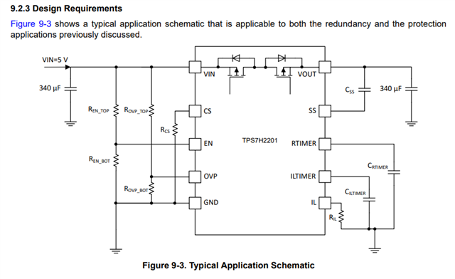
Firstly, I tried to use the proposed design given in the datasheet and made necessary calculations in order to choose the resistor and capacitor values.

My preferred values are given below:

Ren_top: 100K, Ren_bot: 16K6,

Rovp_top: 100K, Rovp_bot: 12K95,

Rcs: 41K5

Css: 150nF

Crtimer: 220nF

Ciltimer: 2n2F

Ril: 6K81

There is no input and output capacitors.

When I tried to simulate the proposed design circuit by using the pspice simulation model, I could see all expected results according to the load change.

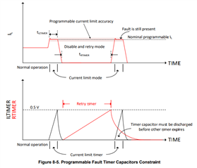
For example, the power switch is in current limit operation with a specified timer and turned off, then its retry mode is activated and those operations works continuously during a heavy load condition.

When I built the same circuit on a PCB, I could not see the expected results. During the heavy load or short circuit condition, the power switch is in current limit operation and its retry mode is activated in only one time.

Then, the power switch is turned off and it is not turned on during a light load. It can only be turned on with grounding to the EN pin of the IC.

Then, I tried many configurations given below to test the IC.

- I added 220uF input and output capacitors, no change occurred,

- I only adjusted the retry timer with 10uF capacitor, no change occurred,

I only adjusted the current limit timer with 220nF capacitor, no change occurred,

- I decreased the current limit with 33K resistor, no change occurred,

How can this problem be happened and what should we do to solve it?

  • Hey Cihan,

    What were the parameters you were designing to when choosing your values?
    What was the current limit you expected?
    What value is heavy load condition?
    Is RTIMER connected to ground instead of a capacitor which would cause it to need power cycling through the EN pin?


    Do you have a schematic so we can verify that all resistors and capacitors are in their correct position?

    Thanks,
    Daniel

  • Hi Daniel,

    In the previous post, I explained that I used the typical application circuit proposed in the datasheet by TI and chose the neccessary resistor and capacitor values according to it. You can check the below circuit given in the page 33 of the datasheet.


    You can find my answers to the questions below:

    What were the parameters you were designing to when choosing your values? 
    What was the current limit you expected? 

    Current limit value: 6A, Current limit timer: 1.1ms, Retry timer: 110ms. Actually, those values can be changed with the design requirements, so it shouldn't cause unexpected results.


    What value is heavy load condition?

    This value can be the minimum resistor value that triggers the overcurrent protection. For example, Rload = 0.8R at 5V or it can be tested with short circuit connection.


    Is RTIMER connected to ground instead of a capacitor which would cause it to need power cycling through the EN pin?

    In the previous post, I shared the "Crtimer" capacitor value like 220nF.

    I also shared my 4 different test configurations in the previous post. Please check them carefully and give me a reasonable solution about the reasons of this problem.

    I can see the current limit and retry operations in only one time and then the power switch is turned off permanently. Maybe your EM parts can be problematic or there is a case that causes this unexpected result.

    I'm looking forward to see a good solution proposed by TI.

  • Hi Cihan,

    Would you be able to share your layout and the production/PCB schematic(s)?

    Thanks,
    Elizabeth

  • Sorry, I cannot share my PCB design file because of privacy rules.

    Can you say the reason of this request? What is your doubt about my PCB design?

    Let me clarify that if there was a PCB design fault, we could see a malfunction on some features of this IC such as disabling device, protection failure, etc.

    When I tested the proposed application circuit on my PCB design, I could see that overcurrent and overvoltage protection, current limit and retry, enabling/disabling the device features worked constantly. However, it is seen that current limit and retry feature only works for once (not continously) and then the power switch is disabled permanently. I think PCB design fault cannot cause such a result.

    In addition, you can be sure that I followed the rules provided with the datasheet given below except that there is no input & output capacitors in my design. I'm using a proper power supply for 5V VIN and even if I added these capacitors, I couldn't see any change on this problem.

    Please give me a consistent opinion that will cause to occur such a problem about current limit and retry feature.

  • Hi Cihen,

    Are you able to share scope shots of rtimer and ltimer? Scope shots of these values will verify if the C_RTIMER and C_ILTIMER capacitors are charging correctly.

    Thanks,
    Elizabeth

  • Hi Elizabeth,

    I couldn't say that C_RTIMER and CILTIMER didn't work properly in my previous post. I can see that both timer capacitors are charged to 0.5V and then discharged. Sorry, I will need to repeat again that the current limit and retry feature is only working for once (not continuously).

    According to the datasheet given below, it should be worked with continuous operation during a fault condition at VOUT. I haven't seen this feature yet.

    Please focus on the cases that will cause such this problem (maybe internal failure of IC or external factors).

  • Hi Cihen,

    The mostly likely case would be a physical short on the board which is why I asked for the schematic, layout, and scope shots - all which could point me to finding the cause of the problem.

    Have you tried replacing the device on the board with the issue?
    Are you seeing this behavior on more than 1 board?

    Thanks,
    Elizabeth

  • Hi Elizabeth,

    Unfortunately, I will say that there is no physical short on the board since I controlled it before test. According to the test results, all functions are working properly except the problem that I mentioned above post.

    You can find my answers to the questions below:

    Have you tried replacing the device on the board with the issue?

    Since I'm not sure exactly, I haven't replaced the IC with the new one yet. If I don't get an exact solution for this problem, I will try to replace with the Flight Model (FM) part since I think that all ordered EM part may have this problem.


    Are you seeing this behavior on more than 1 board?

    No, one board was assembled.

  • Hi Cihen,

    Thanks for getting back to me. I'm working on my end to try to recreate the fault to determine the source of the problem. Let me know if changing devices on the board corrects the behavior or if the problem still persists with a different device.

    Thanks,

    Elizabeth

  • Hi Elizabeth,

    Thanks for your attention. I hope you can create the same fault and give me good news about solution. If there is a change in my side, you can be sure that I will inform you as soon as possible.

  • Hi Cihan,

    Elizabeth will be out of office until next week and will be able to continue lab tests when she returns. Until then, I would like to check a few things with you in case we can resolve this issue sooner.

    I see from your earlier post that RTIMER did successfully charge and discharge once. Can you confirm that RTIMER was discharged before the second time ILTIMER reached 0.5V? If RTIMER was not discharged before the next time ILTIMER reached 0.5V, then it could prevent the retry feature from initiating again unless EN is toggled. 

    Apologies if our questions sound repetitive. Without seeing the exact same lab scopes and PCB design as you, we need to be very detailed in order to narrow down the likely cause. 

    Thanks,

    Sarah

  • Hi Sarah,

    I hope Elizabeth can find a solution quickly as soon as she returns back. I can understand your question; but I also considered the case that you mentioned.

    You can check my preferred parameters (C_ILTIMER: 2.2nF & C_RTIMER: 220nF) with the equation given below:

    I think my capacitor values meet the requirements of the above equation theoretically. If I'm wrong, let me know please.

    Unfortunately, I need to say that I couldn't see ILTIMER operation secondly, so I cannot verify whether the above case is correct or not in reality.

  • Hi Cihan,

    A quick way to verify whether this is happening or not would be to update the RTIMER capacitor value to match the ILTIMER capacitor. If this fixes the behavior then it is likely that C_RTIMER isn't discharging before ILTIMER reaches 0.5V. 

    In theory, the values you selected should be ok. But this test will help us narrow down the possible causes of the unexpected behavior you're observing.

    Thanks,

    Sarah

  • Hi Sarah,

    I can understand your doubt; but I have tested this case before. According to the first post, I shared my four different configurations related to tests.

    I changed C_ILTIMER with 220nF value and made C_ILTIMER and C_RTIMER same; but no change occurred.

  • Hi Cihen,

    As I work to find a solution on my side, were you able to replace the part on your board? And if so, did the problem persist with the new IC?

    Thanks,

    Elizabeth