This thread has been locked.

If you have a related question, please click the "Ask a related question" button in the top right corner. The newly created question will be automatically linked to this question.

LM3414HV: Thermal Issues

Part Number: LM3414HV
Other Parts Discussed in Thread: TPS922052, TPS922053

Tool/software:

Hi Steven, 

I hope you are well.

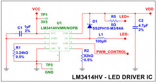
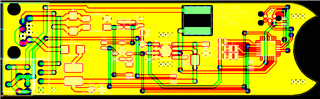
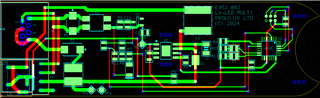
I have currently adapted the design with the LM3414HV IC and have had a PCB manufactured.

Please see circuit diagram below:

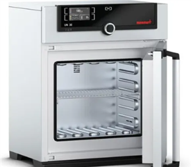
I have tried to run the DUT at 25 degrees C ambient in a thermal oven and it goes into thermal shutdown after 25 minutes.

Any idea what the issue could be?

The PCB is double-sided and 1oz copper.

Kind Regards,

Yousuff.

  • Hi Yousuff,

    Sorry. I am currently out of office. I will reply to you next Monday when I am back to office. Thanks for your understanding.

    Best Regards,

    Steven

  • Hi Yousuff,

    Sorry for the late response.

    May I understand what is your input voltage, LED voltage and LED current? What is the status of PWM_CONTROL signal when you are doing the test?

    Best Regards,

    Steven

  • Hi Steven,

    Input Voltage 48V

    LED Voltage 36V

    LED Current 1A

    PWM Duty Cycle is 100%.

    Kind Regards,

    Yousuff.

  • Hi Yousuff,

    After the thermal shutdown happens, have you checked if all the components on the board are intact and the board can recover to normal working condition after cooling down?

    Best Regards,

    Steven

  • Hi Steven,

    After thermal shutdown, the components are all still intact and the board recovers to normal working condition after cooling down.

    Kind Regards,

    Yousuff.

  • Hi Yousuff,

    I do not see anything abnormal that could lead to such behavior from your schematic. If you put the device in an open-air environment, will the "thermal shutdown" happen? (By the way, may I understand how you judge this is thermal shutdown, but not other kinds of shutdown?)

    Best Regards,

    Steven

  • Hi Steven,

    In an open air environment at around 24 degrees ambient, we can run the device endlessly with no issues. When we put it in a thermal chamber at 25 degrees, the unit fails after 40 minutes. What could be the cause of this? 

    In terms of thermal shutdown, the LED output just pulses (ON-OFF-ON) and struggles to stay on constantly.

    Kind Regards,

    Yousuff.

  • Hi Yousuff,

    Have you checked if your thermal chamber correctly controls the temperature inside it at 25 degrees constantly?

    Best Regards,

    Steven

  • Hi Steven,

    On researching, I believe that this is not how thermal chambers work. Any excess heat generated by the IC itself will add to the ambient temperature. When setting the ambient temperature inside to 25 degrees, over the period of an hour, at least 5 degrees C is added to the ambient, so it will be around 30 degrees when entering TSD. If the thermal chamber kept regulating itself back to 25 degrees C, you're effectively actively cooling the device.

    Kind Regards,

    Yousuff.

  • Hi Yousuff,

    I understand your point.

    My understanding is that a normal thermal chamber should always regulate the temperature to the target point (25 degrees). Please correct me if I am wrong. Please double check how your thermal chamber behaves.

    Best Regards,

    Steven

  • Hi Steven,

    I can confirm that the heat generated by the IC adds onto the ambient temperature of the internal chamber. If the thermal chamber kept regulating itself to hold a constant temperature, you are then effectively cooling the device which is not a real-life scenario. The thermal chamber is only 704mm x 585mm x 434mm in dimension:

    If the unit was tested in a conditioned room for example, there is much more space to keep the ambient constant, however as the space inside the thermal chamber is confined to the dimensions specified above, there will be an increase in ambient temperature.

    Thank you.

    Kind Regards,

    Yousuff.

  • Hi Yousuff,

    Could you measure the temperature of the top case (package) of the chip with a thermocouple, both in thermal chamber and in open air condition? Thanks.

    Best Regards,

    Steven

  • Hi Steven, 

    The temperature of the top case (package) is 100.5 degress C in the thermal chamber. In open air it is 72.1 degrees.

    Kind Regards,

    Yousuff.

  • Hi Yousuff,

    Input Voltage 48V

    LED Voltage 36V

    LED Current 1A

    PWM Duty Cycle is 100%.

    Based on the case temperature you measured and your application condition, I would say the conduction loss of the internal switching FET is too large in this condition considering you are using a large Vout/Vin ratio and the R_LX of this device is 1.8ohm (max).

    I would recommend you using a device with a smaller switching FET on resistance like TPS922052 / TPS922053.

    Best Regards,

    Steven

  • Hi Steven,

    What is meant by the R_LX of the device? In terms of conduction loss, are you referring to the switching frequency? I noticed that the higher the switching frequency set with R_FSW, the more heat generated by the IC.

    What would be the benefit of using a device with a smaller switching FET?

    Kind Regards,

    Yousuff.

  • Hi Yousuff,

    Sorry. I am currently out of office. I will reply to you tomorrow when I am back to office. Thanks for your understanding.

    Best Regards,

    Steven

  • Hi Yousuff,

    R_LX means the resistance across LX and GND when main switch turned on. Please refer to below parameter from Section 6.5 Electrical Characteristics from the datasheet.

    In terms of conduction loss, are you referring to the switching frequency? I noticed that the higher the switching frequency set with R_FSW, the more heat generated by the IC.

    Conduction loss does not have any relationship with the switching frequency. The situation you noticed (more power loss with higher switching frequency) is due to the switching loss. These are two types of loss that mainly contribute to the power loss of such a switching-type LED driver with integrated power FET.

    What would be the benefit of using a device with a smaller switching FET?

    The benefit of using a device with smaller switching FET on resistance (same thing as R_LX) is that it will have less conduction loss.

    Best Regards,

    Steven

  • Hi Steven,

    Am I right in assuming that both these types of losses contribute to the heat generated by the IC?

    Kind Regards,

    Yousuff.

  • Hi Yousuff,

    Yes. You are correct.

    Best Regards,

    Steven

  • Hi Steven,

    Thank you for confirming the above. 

    Is the R_LX the same as R_DS ON on a MOSFET?

    Kind Regards,

    Yousuff.

  • Hi Yousuff,

    Yes. The R_LX and R_DS(ON) that we are talking about here refer to the same thing.

    Best Regards,

    Steven