This thread has been locked.

If you have a related question, please click the "Ask a related question" button in the top right corner. The newly created question will be automatically linked to this question.

TLV431B: TLV431B leakage current is higher than datasheet specific

Part Number: TLV431B
Other Parts Discussed in Thread: TLV431, ATL431

Tool/software:

Dear Expert

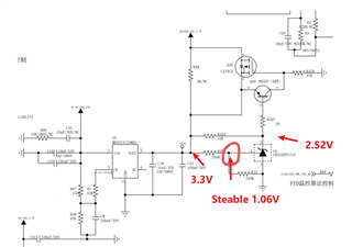
Below is sch ,and TLV431BIDBZR was used as a comparator to output 3.3V to LDO as an overvoltage protection circuit. It was found that comparing with LR432BTLT1G would turn on the error protection transistor, and it is suspected that the leakage current of TI's TLV431 exceeds the specifications.


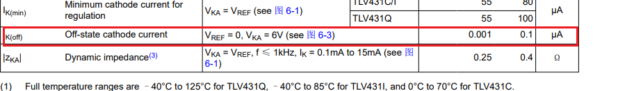
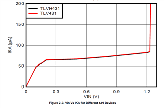
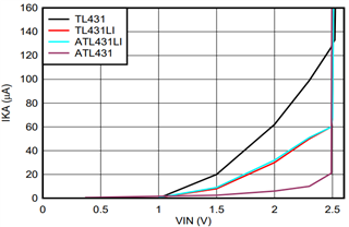
·The measured TLV431 has a cathode leakage current of 66uA when the anode is grounded and the Ref input voltage is 1.06V, which is significantly different from the 0.1uA specified in the specification book;
·The customer has ordered 100 units in bulk, and the situation is consistent;
·Replacing with a new TLV431 resulted in consistent customer failure.

  • Hi Gabriel,

    Thank you for your question!

    The graph below highlights the relationship between IKA vs Vref for the TLV431:

    As a result, for Vref = 1.06 V, about 66 uA of current is the expected behavior in this condition.

    For further analysis, what is the required IKA current specification and is 1.24 V at the reference pin a must have?

    I hope this helps!

    Best Regards,

    Andrew Li

  • Dear Andrew

    Got it, Ika should below 10uA to prevent the transistor from opening ,it should be as low as possible.

    1.24V Ref pin should exist ,so it could work as a compare to open the TLV431 to shut down LDO output .

    And what's your graph source there ,i could found in the datasheet?

  • Hi Gabriel,

    Thank you for the information!

    The ATL431 device is recommended for this requirement as it has the lowest Ika for this Vref value.


    This graph can be found in this app note: https://www.ti.com/lit/an/snvaa58/snvaa58.pdf?ts=1729614865935&ref_url=https%253A%252F%252Fwww.google.com%252F

    Since the ATL431 device has a reference pin threshold voltage of 2.5 V, the 200 kOhm and 100kOhm (R12) resistors next to the Vref pin would need to be adjusted to meet this threshold.

    Please let me know if you have any more questions, and I hope this helps!

    Best Regards,

    Andrew Li