This thread has been locked.

If you have a related question, please click the "Ask a related question" button in the top right corner. The newly created question will be automatically linked to this question.

TPSM83102: I2C bus information missing from datasheet

Part Number: TPSM83102
Other Parts Discussed in Thread: TPSM83100

Tool/software:

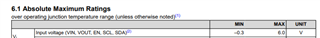
The datasheet for the TPSM83102/3 has generic information on the I2C bus, but nothing specific.  The eval board documentation gives data on the registers and defaults that are left off of the data sheet.  This is inconvenient but manageable,  However there are no electrical specifications for the I2C interface.  Specifically, the eval board shows pull-up resistors to an external 3.3V supply that presumably would come from whatever you use as your I2C programming module.  However, the buck-boost can run from a wide range of input voltages, so it is difficult to know what is the acceptable operating voltage range for this bus - there one that is defined?  Does it depend on the input voltage to the device?  To be specific, I have a board where there is already and I2C bus where the resistors are pulled up to 1.8V.  Can I use that without level translation?   

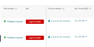
Also, note that the datasheet currently lists as the Orderable Devices as being TPSM83100SIUR and TPSM83101SIUR, rather than the TPSM83102SIUR and TPSM83103SIUR.  Elsewhere in the forum people noted that the web page for the TPSM83100SIUR links you to the data sheet for the TPSM83102SIUR and someone from TI claimed that the problem is fixed, but it is not.  So, the data for these different parts, which are similar, have some configuration management issues.

  • Hi, Alan,

    It is a general I2C block internal, so just follow the guider of standard I2C communication shoule be fine, in DS, we also indicate acceptable ABS voltage of SCL and SDA. 

    1.8V is ok.

    Do you have some details about the wrong orderable device and datasheet in ti.com? From my side, seems all is correct as screenshot below.

    Regards

    Tao

  • Thanks for your response.  First, when I look at the Electrical Characteristics in the data sheet, I see voltage levels for the Enable and Mode pins, but not SCL and SDA.  Where is the voltage levels for these signals in the data sheet?

    The second question about the orderable parts is a bit confusing but I tracked it down.  I looked at the data sheet that you get from the launch page for the TPSM8302/3, and you do get the correct orderable parts at the end of the data sheet.  However, if you go to the launch page for the TPSM83100 at https://www.ti.com/product/TPSM83100?keyMatch=TPSM83100&tisearch=universal_search&usecase=GPN-ALT, and then click on the link for the pdf data sheet, you get something that is actually the data sheet for the TPSM83102/3, but in the Package Option Addendum section it lists the TPSM83100/1. Both data sheets are marked as being SLVSH12-August 2024.  On the Mouser web site they have a saved data sheet for the TPSM8300/1, which is marked as SLVSGY6A with a revision date of June 2023.

  • Hi Alan,

    See the ABS limit in section 6.1 in DS as below. since it is a standard  I2C block, i think you can just take the Basic guide to I2C as ref.

    I click the datasheet link in your attched web page, from my side, datasheet is correct as below. So i am confused what happened. 

    Regards

    Tao