This thread has been locked.

If you have a related question, please click the "Ask a related question" button in the top right corner. The newly created question will be automatically linked to this question.

TPS25751: programming BQ25792 through TPS25751

Part Number: TPS25751
Other Parts Discussed in Thread: BQ25792, BQ25798, , TPS25750

Tool/software:

Hi, 

is it possible to program  BQ25792 through TPS25751 via I2C from uController? Because direct access from uController to BQ is difficult as this chip is controlled by TPS25751 (master).

Or do we have to live with default settings in the BQ device?

Best regards

  • Hi Schroedinger, 

    TPS25751 comes with integrated I2C control over BQ25798. You can easily set the configuration through the USBCPD Application Customization Tool linked here: https://dev.ti.com/gallery/search/usbcpd 

    On the questionnaire page of the tool it'll ask a couple basic questions to configure the BQ25798 settings including charge voltage and current: 

    Details on the specific registers configured can be found in the TPS25751EVM User Guide starting on page 26 (Section 4.2.2 Setting up with BQ25792/8EVM): https://www.ti.com/lit/ug/slvucp9a/slvucp9a.pdf?ts=1729615152658&ref_url=https%253A%252F%252Fwww.ti.com%252Fproduct%252FTPS25751 

    Let me know if there are any further questions or concerns! 

    Thanks and Regards,

    Raymond Lin

  • Hi Raymond, 

    may be my question was not precise enough. My question is, whether I can access a certain register in the BQ25792, e.g.  17h REG17_NTC_Control_0 (data sheet BQ25792, page 53) to adjust the temperature behaviour of the BQ from my uC through TPS25751.  

    All other standard programming through GUI as described above works already perfectly. 

    I know also that I would have to implement a I2C switch, which I want to avoid, to have direct access to BQ from my uC. Because it is not possible to have more than 1 master in the I2C net. 

    Best regards

    Karl Schroedinger 

  • Hi Schroedinger,

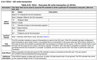
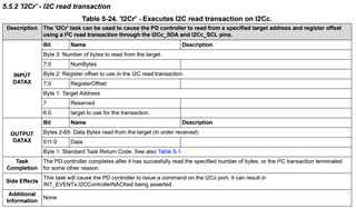
    Thank you for the clarification, yes it is possible to perform I2C passthrough from EC->TPS25751->BQ25798. The EC can utilize 4CC commands "I2Cw" (I2C write) and "I2Cr" (I2C read) to instruct TPS25751 to send an I2C write/read command to BQ25798. 

    Here are some example I2Cw and I2Cr setup with the previous generation device using TPS25750 and BQ25792, the setup is still the same for TPS25751 and BQ25798:

    I2Cw example: 

    <aardvark>
    
    <configure i2c="1" spi="0" gpio="0" tpower="0" pullups="0"/>
    <i2c_bitrate khz="400"/>
    
    <!-- set Aardvark to write to register 0x09 (DATA1) of TPS25750, setting up the I2Cw packet for TPS25750 to write to BQ25792 -->
    <!-- 09 refers DATA1 --> 
    <!-- 05 refers to the size of this I2C write packet --> 
    <!-- 6b refers to the device (Slave) address of the device to write to, in this example 0x6b refers to BQ25792 device address -->
    <!-- 03 refers to the I2C write packet from TPS25750 when I2Cw is sent -->
    <!-- 06 refers to the device register, in this example 0x06 refers to IINDPM register of BQ25792  -->
    <!-- 00 C8 sets the IINDPM of BQ25792 to 2000mA, change these two bytes to set different IINDPM -->
    <i2c_write addr="0x21" count="7" radix="16" nostop="0">09 05 6b 03 06 00 C8 </i2c_write> 
    
    <!-- Optional Step: Reading register 0x09 to make sure data is setup correctly -->
    <i2c_write addr="0x21" count="1" radix="16" nostop="0">09</i2c_write>
    <i2c_read addr="0x21" count="6"></i2c_read>
    
    <!-- sending I2Cw command to register 0x08 (CMD1) of TPS25750 to execute 4cc command -->
    <!-- 08 refers CMD1 -->
    <!-- 04 refers to size of this I2C write packet --> 
    <!-- 49 32 43 77 decodes to 'I2Cw' from hex to ASCII --> 
    <i2c_write addr="0x21" count="6" radix="16" nostop="0">08 04 49 32 43 77</i2c_write>
    
    <!-- Reading the 4 bytes of CMD1 for 00 to indicate command is successfully executed -->
    <i2c_write addr="0x21" count="1" radix="16" nostop="0">08</i2c_write>
    <i2c_read addr="0x21" count="4"></i2c_read>
    
    </aardvark>

    I2Cr example: 

    <aardvark>
    <configure i2c="1" spi="0" gpio="0" tpower="0" pullups="0"/>
    <i2c_bitrate khz="400"/>
    
    <!-- set Aardvark to write to register 0x09 (DATA1) of TPS25750, setting up the I2Cr packet for TPS25750 to read to BQ25792 -->
    <!-- 09 refers DATA1 --> 
    <!-- 06 refers to the size of this I2C write packet --> 
    <!-- 6b refers to the device (Slave) address of the device to read to, in this example 0x6b refers to BQ25792 device address -->
    <!-- 06 refers to the device register, in this example 0x06 refers to IINDPM register of BQ25792  -->
    <!-- 02 refers to the size of the device register, in thsi example register 0x06 is 2 bytes (refer to BQ25792 datasheet) -->
    <i2c_write addr="0x21" count="7" radix="16" nostop="0">09 06 6b 06 02</i2c_write>
    
    <!-- sending I2Cr command to register 0x08 (CMD1) of TPS25750 to execute 4cc command -->
    <!-- 08 refers CMD1 -->
    <!-- 04 refers to size of this I2C write packet --> 
    <!-- 49 32 43 72 decodes to 'I2Cr' from hex to ASCII --> 
    <i2c_write addr="0x21" count="6" radix="16" nostop="0">08 04 49 32 43 72</i2c_write>
    
    <!-- Reading the 4 bytes of CMD1 for 00 to indicate command is successfully executed -->
    <i2c_write addr="0x21" count="1" radix="16" nostop="0">08</i2c_write>
    <i2c_read addr="0x21" count="4"></i2c_read>
    
    <!-- Reading 2 bytes of DATA1 for the output return data from BQ25792 -->
    <i2c_write addr="0x21" count="1" radix="16" nostop="0">09</i2c_write>
    <i2c_read addr="0x21" count="2"></i2c_read>
    
    </aardvark>

    Let us know if you have any further questions or concerns! 

    Thanks and Regards,

    Raymond Lin

  • Thanks, I think I have understood.

    From which document are the tables (5.5...)  in your answer? I didn't find it in the datasheets.

    Karl