This thread has been locked.

If you have a related question, please click the "Ask a related question" button in the top right corner. The newly created question will be automatically linked to this question.

BQ79616-Q1: BQ79616 Uart Communication issue

Part Number: BQ79616-Q1
Other Parts Discussed in Thread: BQ79616

Tool/software:

Hey TI Experts,

We have developed our bms using bq79616 afe. The bq79616 is communicating directly over UART with a stm32 microcontroller. It is made sure all the hardware requirements are fulfilled like adding a logic level shifter.

Once the MCU is powered on wake up sequence is initiated and the afe is now awake. This is confirmed by measuring the voltage on DVDD i.e. we are getting 1.8V on DVDD.

The baud rate of UART is set at 1Mbps.We are using UART receive interrupt to get the data from the Bq79616 response. After the wakeup process, we do the auto addressing. The following are the auto addressing commands:

0xD0 0x03 0x43 0x00 0xF9 0xD4 //step 1 Dummy broadcast write to sync the DLL

0xD0 0x03 0x44 0x00 0xFB 0xE4 //step 1 Dummy broadcast write to sync the DLL

0xD0 0x03 0x45 0x00 0xFA 0x74 //step 1 Dummy broadcast write to sync the DLL

0xD0 0x03 0x46 0x00 0xFA 0x84 //step 1 Dummy broadcast write to sync the DLL

0xD0 0x03 0x47 0x00 0xFB 0x14 //step 1 Dummy broadcast write to sync the DLL

0xD0 0x03 0x48 0x00 0xFE 0xE4 //step 1 Dummy broadcast write to sync the DLL

0xD0 0x03 0x49 0x00 0xFF 0x74 //step 1 Dummy broadcast write to sync the DLL

0xD0 0x03 0x4A 0x00 0xFF 0x84 //step 1 Dummy broadcast write to sync the DLL

0xD0 0x03 0x09 0x01 0x0F 0x74 //step 2 Enable auto addressing mode by broadcast writing CONTROL1=0x01

0xD0 0x03 0x06 0x00 0xCB 0x44 //step 3 Loop through the total number of boards setting the DIR0_ADDR of each board.(We only have single device connected)

0xD0 0x03 0x08 0x02 0x4E 0xE5 //step 4 Broadcast write everything as a stack device first

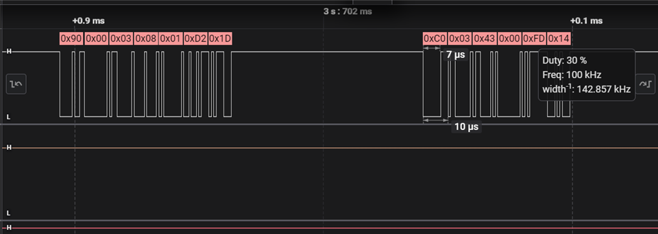
0x90 0x00 0x03 0x08 0x01 0xD2 0x1D //step 5 Totalboard = 1, Hence set device as base and top of stack (COMM_CTRL=0x01)

0xC0 0x03 0x43 0x00 0xFD 0x14 //step 6 Dummy broadcast read to sync the DLL.

After this step we are not receiving any response from BQ79616. What could be the issue? 

The above steps are verified using both the DSO and logic analyzer.

figure 1 - logic level shifter

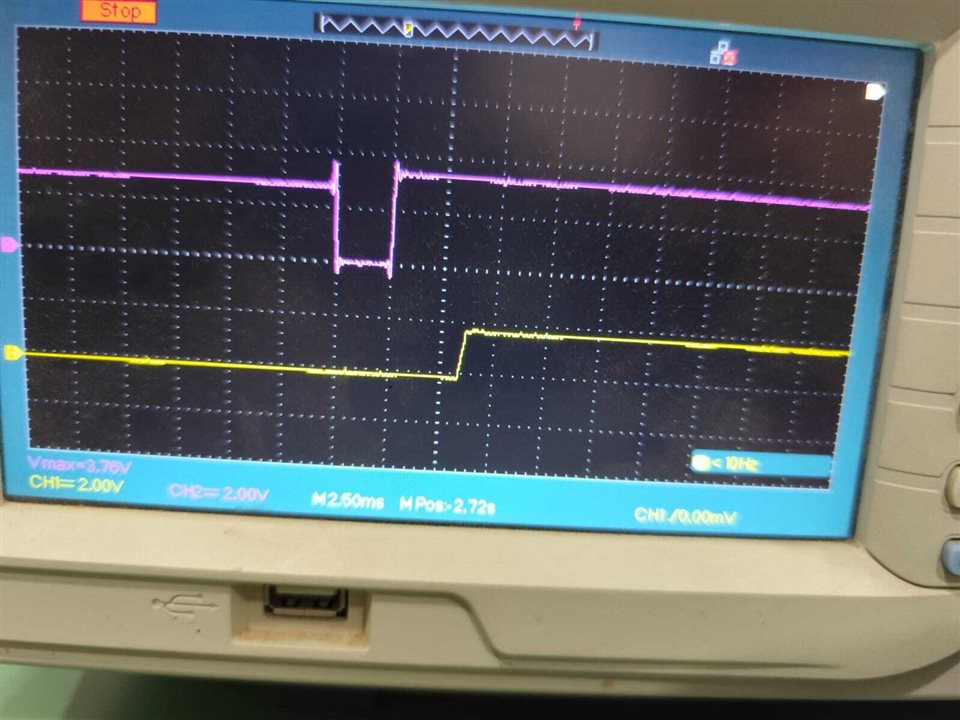
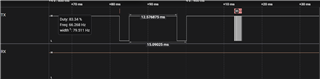
figure 2 - wake up signal (DSO)

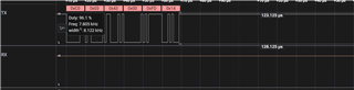
figure 3 - wake up signal (logic analyzer)

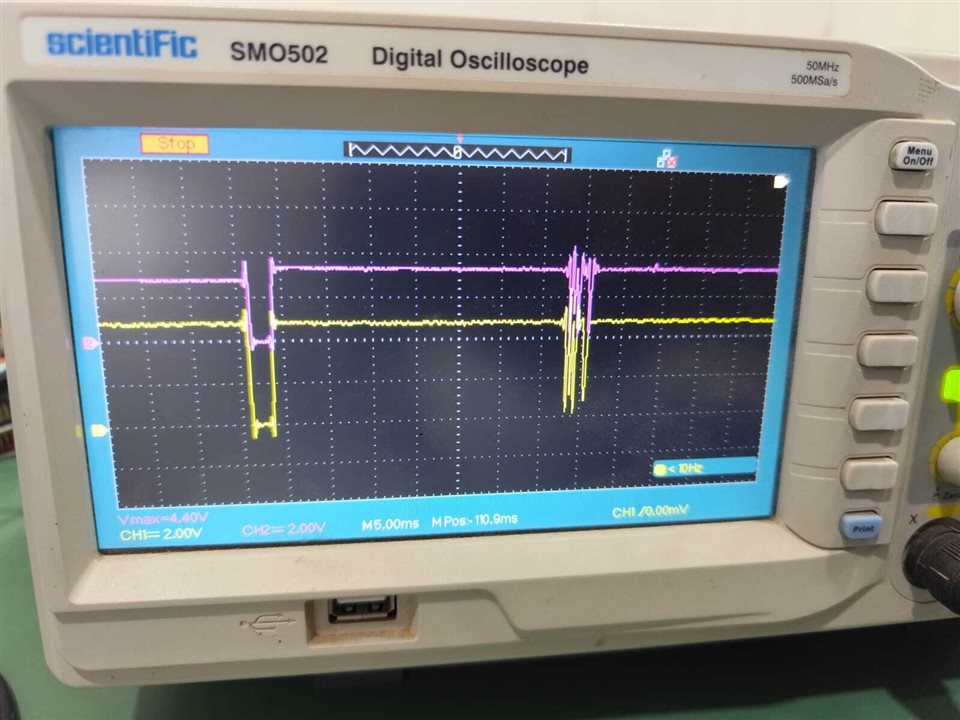
figure 4 - auto addressing (DSO, purple-MCU Tx, yellow- bq79616 Rx)

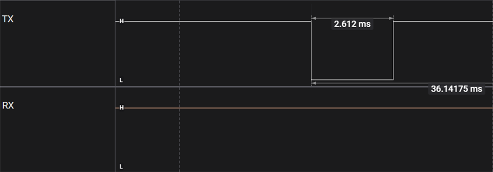
figure 5 - auto addressing (logic analyzer)

The above mentioned observations have been attached for your reference.

Request you to give your valuable response regarding this issue.

Regards

Ibrahim 

  • Ibrahim,

    Attached is a logic analyzer log showing a successful auto-addressing sequence to one BQ79616 using UART. Ensure that the timing between the wake ping and the start of communication is sufficient to allow the board to fully wake up before communication starts. Additionally, sending two wake pings is sometimes necessary and may help.

    Regards,

    Ben

    https://e2e.ti.com/cfs-file/__key/communityserver-discussions-components-files/196/0456.Communication_5F00_with_5F00_one_5F00_616.sal

  • Hi Benjamin,

    We tried out the code with two wake up pings and also increased the timing between the wake ping and start of communication upto 30ms.

    Even with these changes the AFE isn't sending the acknowledgement to the MCU.

    Have attached the images for reference.

    What might be the issue. Waiting for your valuable response on the same.

    Regards

    Ibrahim

  • Ibrahim,

    Can you send me an image of the hardware you are using. I am trying to diagnose if your cable/jumper connections are correct, so if you could show that I may be able to help.

    Regards,

    Ben

  • Hi Benjamin,

    We have the AFE and MCU on the same board. The UART between the MCU & is AFE is not an Off board connection.

    We have a logic level shifter in between the MCU and AFE as the MCU operates at 3.3V and AFE comm at 5V.

    I have attached the schematic snippets for your reference.

    Awaiting your valuable response.

    Thanks and Regards 

    Ibrahim 

  • Ibrahim,

    Could you probe CVDD to ensure that it stays within spec? CVDD powers the communication. Additionally, does the code you have written work on other devices, like an EVM? Could you send the entire Saleae log?

    Regards,

    Ben

  • Hi Benjamin,

    I checked the CVDD and it is properly at 5V. We've used 100k pull up resistors, could this be an issue. Should we have stronger pull-up resistors on the RX & TX lines.

    We have not checked it on other devices or EVM.

    I've attached the Saleae log for your reference.

    Thanks & Regards

    Ibrahim

    salaee log.zip

  • Ibrahim,

    The Saleae log looks good. I do not believe that the commands sent are the problem.

    I am wondering if the voltages on the AFE's RX line are sufficient to register as commands to the device. Could you get a scope shot of the RX pin, if possible?

    Regards,

    Ben

  • Hey Benjamin,

    The CVDD is exactly at 5V, DVDD is at 1.79V after the wake up ping is initiated.

    Also for verification of the commands we tried toggling the TSREF pin and that too works properly.

    It's only the TX pin of the AFE that fails to output any acknowledgement.

    • Note- we are using a logic level shifter in between the MCU and AFE as shown in the schematic I've attached before.
    • Could this have anything to do with this issue.

    Would like you to give your valuable suggestions on the same.

    Thanks and Regards 

    Ibrahim

  • Ibraham,

    Could you try depopulating R18 on your schematic. I've noticed that it is not recommended to pullup TX nor does our EVM pull it up.

    Regards,

    Ben

  • Hi Benjamin,

    We added the following two lines to the example code inspired from the reference manual:-

    WriteReg(0, OTP_ECC_DATAIN9, 0X00, 1, FRMWRT_ALL_W);
        WriteReg(0, OTP_ECC_TEST, 0X00, 1, FRMWRT_ALL_W);

    Earlier in auto addressing we were not writing these registers but once these lines were included we started getting the response from the afe on the AFE Tx lines. In the sample code provide by TI, dummy broadcast write to OTP_ECC_DATAINx register to sync the DLL. But in the software ref manual they did dummy broadcast write to OTP_ECC_TEST register to sync the DLL.

    Now after we remove these two lines, it still works perfectly. So, was these two registers writing mandatory just for once.

    Could these two registers be the solution to our problem or could there be something more to it.

    Request your valuable response on the same.

    Thanks 

    Regards

    Ibrahim

  • Ibrahim,

    If this fixed your issue with communication, it is likely solved. These writes help synchronize the devices so that they can recognize data from each other. It is likely that one of your devices was desynchronized enough that running the extra synchronization got them in line.  

    Regards,

    Ben