This thread has been locked.

If you have a related question, please click the "Ask a related question" button in the top right corner. The newly created question will be automatically linked to this question.

TPS28225: TPS28225

Part Number: TPS28225

Tool/software:

Hi, I have this issue which is somehow related to the driving method of the PWM input of TPS28225 .

As a background, we are using a PWM output from STM32 of 240kHz at a duty cycle of 10% to 18%. Thus, 3.3V PWM levels.

Also, I am utilising the pull-down resistor of 3.5kohm (R1 on the diagram) to disable the 3-state input mode as described on the design notes. However, there are instances that the outputs are not activated even though the PWM is driven to the gate driver.

At the moment, I am still investigating how the PWM output is set after a PWM drive ends - either floating or being set to a defined low level. But, so far by looking at the oscilloscope trace, it seems to be left floating for a period of time. I need to confirm this with FW colleagues.

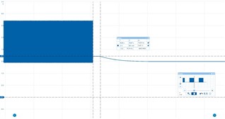
Looking at the trace, at the attachment, I can't seem to comprehend why there is a 0.451V after the PWM end. However, if I removed the pull-down completely, that goes up to 2.4V which actually solves the inconsistenly of driving the output.

  • Hello Ed,

    Thank you for the input. By looking at the trace it looks like the controller must be high impedance after the pulse train. It would be preferable if the PWM pulls low on the last pulse just to avoid any possible condition that can set up the tri state. Some considerations to confirm which can be detected as a possible tri state. Make sure the PWM inputs have a fairly fast rise and fall time, if the slew rates are low this could be detected as a tri state. 

    It sounds like that if you remove the pull down resistor on the PWM input that the driver outputs operate as expected, please confirm.

    Regards,

  • Hi Richard, thanks for the response. Yes, highly agree that PWM controller is set to high impedance but I am not quite sure where the 0.45V comes from. If we consider the internal voltage divider network on TPS28225 IC - it would be more than that - [ Vdd = 5V, Rpu = 27k, Rpd = 13k] Vin = (5V*13k)/(13k+27k) = 1.6V.

    Also, in terms of slew rate, as far as I checked, it is less than 250ns.

    Yes, removing the external resistor  = 3.5k, it operates as expected.

  • Hello Ed,

    Thanks for confirming, that removing the 3.5K resistance seems to resolve the issue. In looking at the schematic and resistor values, I think the external 3.5K would be in parallel with the internal 13K. That being the case the PWM would be Vin=5V x 2.76K/(2.76K+27K)=0.46V. So it looks like what you see with the added 3.5K is what we would expect.

    The one think I see also, is that in the datasheet 3.5K or less is listed as the resistance where tri state should be disabled. Can you try lower than 3.5K, such as 3K to see if the 3.5K may be marginal. 

    There is an existing FAQ on the TPS28225 you might want to check also.

    https://e2e.ti.com/support/power-management-group/power-management/f/power-management-forum/1328077/faq-tps28225-what-are-the-design-considerations-for-the-tps28225-s-3-state-pwm-input

    Regards,

  • HI RIchard,

    Yes, thanks for confirming.. My bad, with 0.46V, that has the 3.5K added which should be on the calculation.

    I'll try with Pull down lower than 3.5k and get back to you.

  • Hi Ed,

    No concerns, let me know if the experiment with the lower pull down works, go ahead and try a couple of values if not initially successful.

    Regards,