This thread has been locked.

If you have a related question, please click the "Ask a related question" button in the top right corner. The newly created question will be automatically linked to this question.

TPS7A96: PG Signal Driving LED

Part Number: TPS7A96

Tool/software:

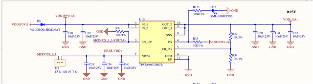
I am trying to determine why D37 does not appear to turn on when the board is powered on. I am measuring 1.78V at the PG pin but I would expect that it should be 3.3V with the 10kOhm pull up. Why I am seeing 1.78V?

  • Hello,

    Thank you for your question.

    What is your input reading as? 

    According to the schematic it seems like there is significant load current, which could be driving the input lower than expected.

    Best,

    Hannah

  • Hi Hannah,

    Thanks for reaching out. Can you please clarify what you mean by input reading and load current? There is only a small load on the power supply output.

    Best,

    Ariana

  • Hi Ariana,

    What current load is used in the circuit? In the schematic it states 1A, which is the only load I see.

    I mean to measure the input and clarify if the input is measuring as is stated and not less than.

    Best,

    Hannah

  • Hi Hannah,

    I work with Ariana. The load is small, 1A is notated there as the maximum possible load. In the current setup, the load is maybe 100mA maximum. 

    Can you explain why the load matters? We are not exceeding the rated load, the output is reaching the target voltage. The question is about the PG pin, why is pulling up to only 1.8V? 

    The data sheet has some verbage not very clear to me, it says PG will "asset" after reaching the threshold voltage. What does "assert" mean? Is it with transistor off the bus pulled high? Or so we have to reverse the LED connection if asset means transistor on, and sink the current into the PG pin. It is not clear to me.

    Thanks,

    Arnav

  • Hi Arnav,

    Originally, I said to check the input voltage, because a large load can bring down the input and according to the schematic this input is connected to the PG pin, which could be why you are seeing a lower voltage than expected on the PG pin, but I don't suspect that with the load. It could still be a good idea to verify that the input is at the expected 3.3V, just to ensure the input is not affecting the voltage you are seeing at the PG pin.

    Additionally, have you tried a different device, i.e. through a device swap? It could be good to see if this error is just happening with this device. 

    I also noticed in the datasheet that it states that, "The FB_PG pin programs the PG pin and serves a dual purpose of programming the PG threshold assert voltage", please see this thread: (8) TPS7A96: PG Trip Point - Power management forum - Power management - TI E2E support forums

    Best,

    Hannah

  • Hi Hannah,

    The input voltage I saw was 3.22V and after power cycling it was 3.31V. The 1.78V reading was measured from R33 and R151 when the input voltage was 3.22V.

    Best,

    Ariana

  • Hi Ariana,

    Thank you for checking this for us. 

    Please allow me a business day to look into this for you.

    Best,

    Hannah

  • Hi Hannah,

    That thread doesn't directly answer my question but its okay, PG is pulled high when the fb_pg pin is above 0.2V. Thats fine, so we have the LED implemented correctly. We also verified the PG goes high with the Ti EVM.

    The fb_pg resistor dividers we use are top and bottom both 10kohm giving a .465V at the pg_fb pin which we measured to be around .462, so that is working. The PG should be asserted high. But the threshold is set to only 43% of vout, maybe this is too low? 

  • Hi Arnav,

    It definitely could be possible that because the threshold is set to 43% of Vout that you are seeing 1.78V at the PG pin.

    Is there any way you can try to fix the threshold and let me know if this fixes this issue?

    Best,

    Hannah