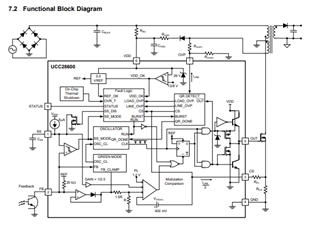
This thread has been locked.

If you have a related question, please click the "Ask a related question" button in the top right corner. The newly created question will be automatically linked to this question.

UCC28600 Repeatedly in millisecond range entering soft start performance

Part Number: UCC28600


Tool/software:

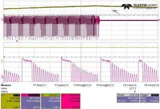
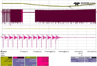
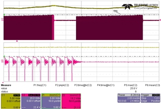
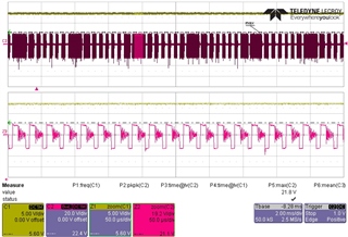
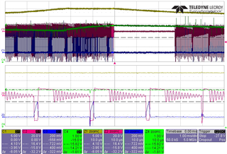
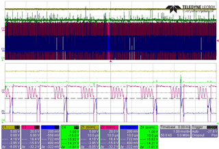
A design using UCC28600 to run from 85VAC to 265VAC or 400VDC I experience that at certain combinations of load and input voltage the output voltage exhibit drop and recovery within roughly 20ms (it is proven independent from the mains period as a non steady phase shift occurs between the mains input voltage and the drop/recovery pattern).

In a semistatic pattern I will see expected regulation for a few milliseconds, then roughly 2.6 milliseconds of no switching activity while the out put drop from nominal 15V to 13V when the reduced PWM starts, unable to support theactual load thus seeing further output voltage drop to approx 10V when the PWM achieves sufficient pulsewidth to reverse the voltage drop until finally normal regulation occurs, just to repeat the cycle.

  • PFF_hickup_20241023.pdfro-5100.hw.pfc.sch_revf1.pdf


    SPD-223-014-ROV_Aux_Transformer_Spec_alternative_1.0.pdf

    In reply I was able to upload Screenshot, schematic (page 2 is relevant fior this question) and transformer specification

  • Hi Flemming,

    Thank you for reaching out.

    I will review the flyback piece of the schematic and get back to you today.

    Regards,

    Harish

  • Hi Flemming,

    Can you please share the output power/ voltage here?

    Also there is a calculator with this IC, did you have a chance to use this in your design?

    https://www.ti.com/product/UCC28600#design-tools-simulation

    Regards,

    Harish

  • Thank you for the prompt reply,

    I must admit not to be the original designer of the current implementation, but I have tried to follow the tracks of the original designer including utilizing the mentioned tool.

    Regulated output voltage is 15V, and nominal power is 70W

    I have attached the excel file of the tool with my attempts of replicating the actual circuit.

    slvc104j_20211101.xls

    Regards

    Flemming

  • One missing detail:

    A major part of the load is a speed controlled fan, hence the output power will vary (slowly) between 10W and 70W

  • Hi Flemming,

    Thank you for providing the details.

    I reviewed the schematic, looks like there is R24 which is 10k resistor and is too much. This could add a big offset to the CS pin limiting power here and causing shutdown. Maybe try reducing this to 1k and see what happens.

      Also transformer Nps turns ratio and Lm looks suboptimal. A higher turn turns ratio might be needed here. Please refer the optimal parameters attached in the sheet below and let us know your observations.

    8420.slvc104j.xls

    Regards,

    Harish

  • Thank you for the prompt update.

    The R24 is 1400 Ohms, noted as 1k4 using the k as radix point.

    I believe the suboptimal windings ration was chosen not to surpass the MOSFET maximum offstate voltage when running the circuit off the PFC output voltage of 400VDC.

    As I am not able to wind transformer myself, the test of your suggestions will take some time.

    I will surely return when I have had the opportunity of implementing the suggested updates.

    Regards,

    Flemming

  • I note that in the suggested transformer design has a lower ratio of bias winding compared to main output, effectively driving the UCC28600 controller off 12V while output is regulated to 15V.

    As the design I have inherited does have the ratios inverted I would like to ask if an additional Over Voltage Protection exist in the UCC causing it to 'semi soft start' if VDD reaches a certain value. I don't remember having seen this value stated in the datasheet.

    Regards

    Flemming

  • Hi Flemming,

    Thank you for reaching out again and clarifying about the 1.4k resistor.

    Before changing the transformer, I would recommend using the excel sheet which I attached to check for Rovp1 and Rovp2 resistors as OVP is sensed through this resistor setting and triggers protection when voltage is greater than 3.75V.  Please check the aux voltage waveform (scaled by these resistors Rovp1/Rovp2) to see if it exceeds this value.

    Regards,

    Harish

  • Hi Harish,

    I do not think the 'normal' OVP is active as I see the same behaviour if I totally remove R13, i.e. configuring OVPin and OVPout to both be infinite.

    Regards,

    Flemming

  • Hi Flemming,

    I would suggest measuring the cause for shutdown - checking the actual waveforms - CS (for primary OCP) and OVP (for load OVP) without BW limit on the probes to verify this.

    Regards,

    Harish

  • Hi Harish,

    Sorry for the long turn-around time.

    I have been looking for correlation between the onset of oscillation in the regulated voltage and either of the protection inputs CS (for OCP), OVP (both for source OVP and Load OVP) only seeing what was turning out to be noise on top of a valid signal (noise due to difficulties in getting a sufficient direct probe connection.

    To supplement the measurement I also experimented with low pass filtering of the input signal for OCP and OVP to no avail.

    What seems to be doing the trick is to lower the VDD for UCC28600 to be in vicinity of 12V.

    The original designer has apparently read the positive maximum threshold voltage for UVP detection as a minimum running supply voltage. hence the transformer ratios are designed to have 12 turns for the Vbias versus 11 turns for the 15V output hence supplying VDD roughly 16.5V nominal.

    All changes were reverted to the original component values but adding 3 diodes in the path supplying the VDD, thus lowering the voltage roughly 2V apparently did the trick (equivalent to removing roughly two turns of the Vbias winding of the transformer).

    Now I have consistent performance over the entire range of 85VAC through 265VAC and 400VDC.

    I seems my only missing point at this time is if a function exist within the UCC28600 reacting to VDD rising above a certain limit.

    I have not been able to find any suuc specification in the datasheet.

    Thank you for the inspiration you have provided

  • Hi Flemming,

    Thank you for the reaching out again. Great to know you were able to resolve the issue for the entire operating range.

    From the documentation as long as Vdd is below the abs max rating of 32V it should be fine and should not trigger protection. I will check internally if there any such spec recorded.

    But can you please post the AUX winding waveform in the working vs hiccup condition (zoomed) as I still think it could be due to output load OVP.

    Regards,

    Harish

  • Hi Harish,

    I would say for certain that the output OVP is not the cause. Screenshot are attached to support my standing.

    The first three screenshots are taken for the original configuration of the flyback converter; at input voltages of 200VAC, 265VAC and 85V respectively

    The second two screenshots are taken for the original configuration of the flyback converter but added a 240k resistor in parallel to R16 (the lower part of OVP attenuator from Vbias winding to OVP input) i.e. a 15% increase in OVP threshold; at input voltages of 200VAC and 265VAC respectively

    The third three screenshots are taken for the original configuration of the flyback converter having R13 removed (the upper part of OVP attenuator), thus leaving the OVP input of UCC28600 fully non-driven; at input voltages of 200VAC, 265VAC and 85V respectively

    I only see steady output voltage at 85VAC input for all three configurations, 200VAC hickups in all three configurations and 265VAC hickups only when OVP input is not driven (but still loaded to ground)

    Original configuration @ 200VAC (hickup)

    Original configuration @ 265VAC(smooth)

    Original configuration @ 85VAC (smooth)

    load OVP threshold increased 15% @ 200VAC (hickup)

    load OVP threshold increased 15% @ 265VAC (smooth)

    OVP disabled @ 200V (hickup)

    OVP disabled @ 265V (hickup)

    OVP disabled @ 85V (smooth)

    Best regards

    Flemming

  • Hello,

    I was asked to look into this for you.  Could you tell me what the waveforms are by channel?

    Regards,

  • Hi Mike,

    Sorry for not including the description of traces:

    Yellow trace is the primary output (the one that has the feedback connection) of +15V QSAUX in the original attached schematic diagram.

    Red trace is the unfiltered (BW 500MHz) output of the winding feeding UCC28600 OVP input and rectifier for VDD, T1 pin 6

    Screenshot upper half is included to indicate whether output voltage is kept smooth, hence has a rather slow scanrate.

    lower half is a zoom allowing judging of overshoot and the like for the OVP input to UCC28600

    Included in the screenshots are also an automatic measurement, taken from the slow scan window, indicating the maximum voltage of Channel 2 (the red trace)

    What I see is that no matter the attenuation from the red trace to the UCC28600 OVP input, the instability occurs whenever the peak voltage measured by the red trace is in excess of roughly 23V.

    This is the reason that I suspect that an undocumented additional OVP function exist that is based on the VDD supply voltage level.

    I think I have read in the datasheet that VDD exceeding 21V nominally would trigger some sort of shunt regulator within the UCC28600, but I saw no warning that activating this regulator would upset the regulation of the device.

    This voltage level is still far below the maximum rating of 32V for the VDD.

    The fact that introducing additional diode drop from three series connected diodes to the D8 eliminates the fluctuation of the regulated output voltage, further convinces me that a VDD based secondary OVP function exist.

    best regards

    Flemming

  • Hello,

    Thanks for the information. 

    Could you tell me what your load conditions are when this happens?

    Could you probe the Aux winding voltage, CS, Output and VDD and trigger on when the output drops out.  Then zoom in on the last three switching cycles.  This should help us determine why this is controller is shutting down.

    Regards,

  • Hi Mike,

    The measurements will not be performed right now as other tasks are at a higher priority but be warned; I will return.

    The loading of the device, when running the test consists of purely resistive loading of outputs +15V QSAUX by 50 Ohm and -15V QSAUX by 150 Ohm returning both at QSGND.

    Over time (some years) the performance has worsened causing the recommended test setup to include a fan (same fan as will be powered in the final application San Ace 80 model 9HV0812P1G001, running idle - input control PWM at 0% duty cycle, nominally pulling 640mA) connected to Fan Pwr and SGND

    The observation being that for some instancies of the board, stable operation was obtained by adding the fan, while it was unstable with ony the resistive loads applied.

    My shot from the hib is that  the transformer over time has been produced with slightly increasing leakage inductance leading to increased voltage overshoot at the bias winding, which to some extend is limited by the fan as fan winding is placed between the final secondary output winding and the bias winding.

    regards

    Flemming

  • Hello,

    Thanks for the information.

    When you have a chance to look into the waveforms let me know.  That should help you figure out what is causing the design to misbehaive.

    I do think you might be on to something with the leakage inductance.  It this is changing it could change the aux winding ringing signature.   If there is too much ringing on the aux winding it could trigger and OVP.  If this is the case you should be able to resolve the issue with RC snubbing across the output rectifier.

    I did review your schematic and you do have snubbers across the output recitifiers.  You could try adjusting those to decrease the rining on the aux winding if it needs to be done.  The other thing that you could try is adding a snubber across the aux diode as well.

    Regards,

  • Please note that I cannot trigger the ordinary OVP as the top resistor of the OVP attenuator has been removed i.e. the OVP pin of UCC28600 has only got the resitor connecting the pin to ground left in the last three screenshots, still exhibiting the OVP like performance.

    Please forgive my persistence: does an undocumented OVP function exist that based on the VDD input triggers a recovery function even when the OVP pin is not given any input?

    Regards

    Flemming

  • Hello,

    The OVP is also used for zero current detect to achieve QR opperation.  So you cannot dissconnect the high side resistor to disable OVP.  If you do this the QR oppeartion will not work and cause the controler to misbehaive.

    So I would reconnect the OVP divider to the aux winding and do the recommended troubleshooting.

    Regards,

  • Hi Mike,

    I've found the time to do some measurements

    In the following screenshots the instability of the regulated output (yellow trace) is visible in the main timebase and, when instability occurs the zoomed timebase will show the last four cycles before collaps.

    When no instability occurs the zoomed timebase will be at a random pick of time.

    Trace colours:

    Yellow: regulated +15V QSAUX

    Red: voltage from Aux winding T1 pin6 (also supplying VDD)

    Blue: Current sense input UCC28600 pin3

    Green: VDD UCC28600 pin6

    OVP has been reinstated althought threshold has been increased by 18% (R13 changed to 330k)

    Still the instability occurs at 200VAC and 265VAC input.

    load OVP threshold increased 19% @ 200VAC (hickup)

    I

    load OVP threshold increased 19% @ 265VAC (hickup)

    load OVP threshold increased 19% @ 85VAC (smooth)

    What catches my eye is the slow increase of VDD until collaps occurs in the 200VAC and 265VAC screen shots, when running smooth at 85VAC the VDD stabilizes just  slightly lower than the maximum detected at 200VAC and 265VAC.

    Adding another load at the regulated +15V QSAUX output valued at 22 Ohms will also change into stable running at all three tested input voltages.

    load OVP threshold increased 19% + output load increased 680mA@ 200VAC (smooth)

    load OVP threshold increased 19% + output load increased 680mA@ 265VAC (smooth)

    load OVP threshold increased 19% + output load increased 680mA@ 85VAC (smooth)

    Unfortunately the increase of idle power consumption is not a viable way forward as it will indeed subtract from the power efficiency of the appliance and from the maximum available output power.

    Best regards

    Flemming

  • Hello,

    Your inquiry has been recieved and is under review.

    Regards,

  • Hello,

    I am collered blind but can see shades.  Coud you tell me what channel each waveform is?

    Regards and thanks,

  • Hi Mike

    In the zoomed part the identification of traces is easier than in the upper slow scan part:

    uppermost is yellow, +15QSAUX regulated output

    next is green VDD at UCC28600 pin6

    next, more square with idle ringing is red, voltage from Aux winding T1 pin6 (also supplying VDD)

    Lower is blue, Current sense input UCC28600 pin3

  • Hello,

    Your inquiry has been recieved and is under review.

    Regards,

  • Hello,

    I cannot disquish between yellow and green on the scope plots.  This is part of the issue of being collored blind.  I can distinquish shades.  So if you let me know what the channels are on the scope plots are measuring this would be hellpful?

    So I do not have to scan through the e2e thread could you repost in this thread with the channel designations?

    Regards and thanks,