This thread has been locked.

If you have a related question, please click the "Ask a related question" button in the top right corner. The newly created question will be automatically linked to this question.

UCC28070A: UCC28070A problem at 255 to 265Vac

Part Number: UCC28070A

Tool/software:

hello,

we are using a Ucc28070A for an interleaved PFC with a mains input of 85-265Vac 47Hz-63Hz and an output of 385Vdc 2KW (5.2A). Switching frequency = 300kHz.

This one works correctly at 2KW up to a voltage of 255Vac, then from 255Vac to 265Vac, the top and bottom of the sinusoid of the input current is not "clean". At this moment an audible noise is generated by the boost inductors (Self planar of 70µH in our application). The voltage of the 385Vdc bus is still OK, it does not drop.

We thought it was the PKLMT that was acting but it is not the case (We increased the low resistance of the PKLIMIT divider bridge).

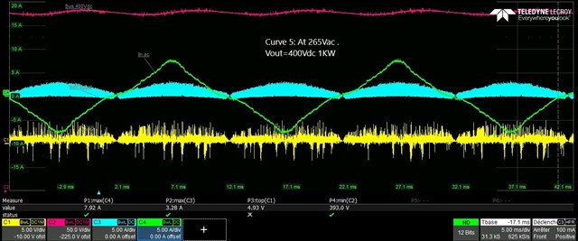
Then we increased the output voltage to 400Vdc to move away from the high rectified mains voltage but the fault remains the same. (See curves)

Then with an input voltage of 255Vac or 265Vac, we lowered the output power. The top and bottom of the sinusoid become correct again for an output power of 900-1000W!. (See curve)

Why do the top and bottom of this sinusoid have this shape despite moving away from the rectified mains voltage?


We noted curves with the bus at 385Vdc and at 400Vdc with the fault. All the curve zooms are taken at the peak of the current sinoid when there is the fault.

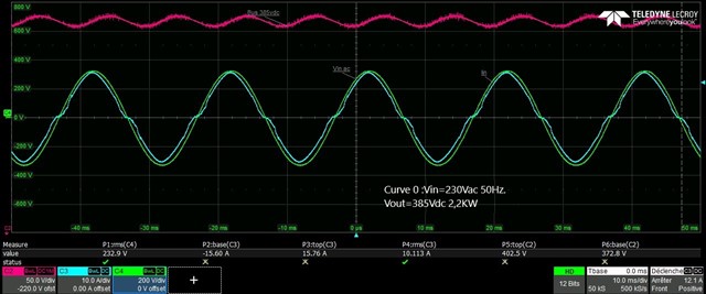
For curve 0: Red curve: Vout, Blue curve: Input phase current, Green curve: Vin=230Vac

                                                                                  Vin=230Vac Vout=385Vav 2KW


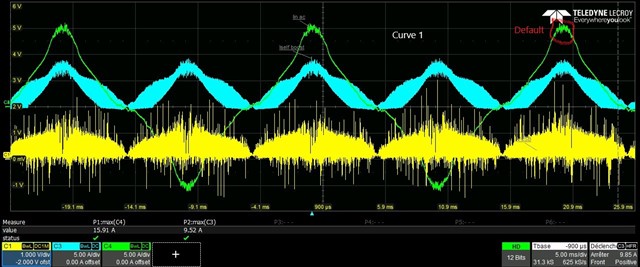
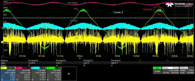
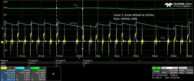
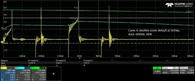
For another curves: Yellow curve: CSB voltage, red curve: Vout, blue curve: self boost B current, Green curve: Input phase current

                        Curve 1  Iin at 265Vac Vout 385Vdc 2KW

                        Curve 2  Iin at 265Vac Vout 400Vdc 2KW

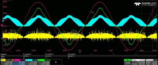
                        Curve 3  Zoom default Iin at 265Vac Vout 400Vdc 2KW

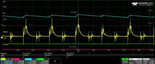
                        Curve 4  Another zoom default Iin at 265Vac Vout 400Vdc 2KW

                        Curve 5  Iin at 265Vac Vout 400Vdc 1KW


  • Hello Thierry, 

    I suggest that you try increasing the value of Rsynth (by trial and error in small increments).  

    Here is the argument why:
    Rsynth programs the down-slope of the synthesized current waveforms presented to the inputs of the current-sense amplifiers. 
    The CSA and CSB (CSx) voltages represent the up-slope portion of the total inductor current and the synthesizer adds in the downslope portion.
    The Rsynth value is chosen so that the downslope matches that of the actual inductor current. 
    The current amplifiers then generate an error voltage (which generates the PWM duty cycles) based on the difference between the average of the inductor current and the IMO reference voltage.   

    At high input voltage peaks, the duty cycle is small and the demagnetization time (down-slope time) constitutes the majority of the average inductor current. 
    A low value of Rsynth generates a steep down slope, while a high value of Rsynth generates a shallow down slope

    At high line with narrow duty cycle an inappropriately steep downslope will understate the synthesized current signal and effectively understates the average amount of current being sensed in the inductor.  If the sensed current is understated, the current amplifier output error signal will be higher and the PWM dutycycle (D) will be increased to make the current representation match the IMO signal. The wider D at peak of high line voltage shapes the actual input current into the extra peaky non-sinusoidal current. 

    Increasing Rsynth will make the synthesized down-slope less steep, so the synthesized voltage representation of the total inductor current will "look" larger at the CAOx input, the error to IMO voltage will be lower so D will be lower.  This should reduce the "peakyness" of the current at the voltage peak of high line. 
    Increasing Rsynth too much will overstate the synthesized current and increase D so much that the line current will start to flatten out at the line peak. 
    There is an ideal value for Rsynth that minimizes THDi.   

    I recommend to optimize the value for Rsynth at the line voltage where it is most important to minimize THDi. Usually that would be at 230Vac (the nominal line where THDi tests are performed).  But you can also reduce THDi at 264Vac without affecting THDi at 230Vac very much. 

    Note: at low line, D is usually the larger portion of the switching cycle, so even a significant error in downslope (up or down) will have little effect on the synthesized current's average value.  It is at narrow D conditions where down-slope error has a large impact on the average, and consequently on the input current shape. 

    On aside note: I recommend to use the tip & barrel probing method to minimize the amount of switching noise pickup on the low-voltage CSx signals. 
    The signals will look a lot cleaner.

    Regards,
    Ulrich 

  • Hello Ulrich,

    Thanks for your quick reply. I modified the Rsynth resistor and I have a more compliant sinusoid.
    I noticed that the Rsynth pin (7) is sensitive to noise, is it true or does it come from our routing?.
    Regards

    Thierry

    Curve now at 265Vac at 2KW

    Zoom

  • Hello Thierry, 

    I am not aware that the Rsynth pin is particularly noise sensitive.  We have not received complaints about that potential issue from other customers. 

    Since the synthesized down-slope is not observable externally, I'm not sure how you can infer that noise might be adversely affecting the down-slope programming.  

    Regardless of how, if it can be shown that noise is affecting the downslope (cycle-by-cycle), it very likely would be a consequence of poor routing of the Rsynth resistor tracks from the pin to the GND net.  Either magnetic coupling to a large loop area or capacitive coupling to a high dv/dt net could modulate the current flowing through Rsynth.  The routing tracks should be kept very short. 

    See Figure 7-10 (page 43) in the UCC28070A datasheet for an example of single-layer pcb routing. Two or more layers can allow even better noise-resistant routing of all control signals.  Be sure to avoid routing high current and/or high-dv/dt tracks or planes below the control signal area. 

    Regards,
    Ulrich