This thread has been locked.

If you have a related question, please click the "Ask a related question" button in the top right corner. The newly created question will be automatically linked to this question.

TLV1117: Thermal dissipation

Part Number: TLV1117

Tool/software:

Hi 

I would like to know if you think if this is part is suitable for what I tray to do. Below is spec

PCB dimension: 28mm x 30mm 

PCB is a 4-layer board

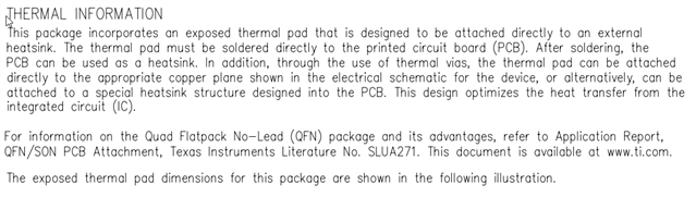
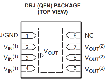
Part: TLV117-50CDRJR  (QDFN)

Vin = 15

Vout = 5V

Output Current = 150mA (Max)

Thermal junction air = 38.2

T = (15-5)*0.15 * 38.2 = 82.45C

82.45 is lower than max temp wich is 125C.

Do you suggest using this part, or do you have alternative part with lower junction temp, or you suggest going with switching regulator.

Thanks

  • Hi Amir,

    You left one important part of the equation out, which is to add to the 82.45C junction temperature rise the ambient temperature. So with this operating condition (and assuming that the device is actually achieving the 38.3C/W RθJA - I'll talk about this shortly), the max ambient temperature that could be supported would be 125C - 82.45C = 42.55C. Now, the JEDEC High-k board layout with which the thermal metrics are simulated is much larger than the 28mm x 30mm board that you are working with (it's 74mm x 74mm), so achieving the thermal metrics posted in the datasheet may not be possible. If your ambient temperature is higher than the 42.55C I calculated, this almost certainly won't work. Since you have a small board, using a more efficient power supply would probably be best - a switching regulator would be better if your system can tolerate the switching noise. 

    Regards,

    Nick

  • Hi Nick,

    Thanks for your quick reply.Yes, I totally forgot to add max unit temp to the calculation.  I rather not use switching regulator but do know any linear regulator with lower RθJA. if not do you have any suggestion for switching regulator which does not require a lot of components.

    Thanks

  • Hi Amir,

    Have you considered the KTT package for TLV1117? It has about 28% better thermal performance than the DRJ package, although it's quite a bit larger. You will see that the trend when you want to get better thermal performance from RθJA in the low 40s or 30s to get to the 20s (C/W) is that the packages will get large. KTT is among the best for thermal performance. 

    I've taken a look through our portfolio and I'm not seeing a better option for your application conditions than TLV1117 in the KTT package. 

    Regards,

    Nick

  • Thanks Nick,

    I have decided to use DFN package base on my calculation the max current I need is 0.1A which put temp on worst scenario(at 40C) at 78.3C which is under 125C.  But i have questions for the layout of this part

    - What does below statement mean, (data sheet page 25), do I need do anything specific. 

    - Do you have layout guideline for QFN package. specifically adding more copper on Vout to reduce Junction temp.

    Thanks

  • Hi Amir,

    I have decided to use DFN package

    Did you mean the DRJ (QFN) package as initially intended? Your math below suggests this package. 

    - What does below statement mean, (data sheet page 25), do I need do anything specific. 

    This statement is pointing out that this package has an exposed metal pad on the bottom that should be soldered to an exposed pad on the board, so to answer your question, yes you need to do this specifically to meet thermal requirements. 

    - Do you layout guideline for QFN package. specifically adding more copper on Vout to reduce Junction temp.

    In general the copper connected to each pin will help to pull heat from the device, but the majority contributor by far is the GND copper connected to the thermal pad, so extending the copper beyond the thermal pad will help significantly, and additionally using thermal vias to connect the thermal pad to the internal GND layer (I assume you only have 1 GND layer with a 4-layer board) will help the thermal performance. 

    Regards,

    Nick

  • Hi Nick,

    The problem is the thermal Pad does not connect to GND in this chip, the thermal pad connects to Vout.

    Below is the 4-layer board locations

    1.Signal/ GND
    2.GND
    3. VCC
    4.Signal/GND

    Thanks

  • Hi Amir,

    I missed that detail (it's only old devices that do this), sorry about that. In that case, yes you were correct, you should try adding as much copper to the VOUT net as possible given your board constraints. What I'm not sure of is how exactly the thermal metrics were simulated for this device because most devices have the thermal pad connected to GND, and the thermal metrics are simulated assuming that the thermal pad is connected to the internal GND layer through vias. I can ask our thermal modeling team to see if they have insights into this.

    Regards,

    Nick

  • Hi Nick,

    Thanks, let me know if your team have any update. 

  • Hi Amir,

    The thermal modeling engineer said that unless it was specifically specified that the thermal pad isn't connected to the internal layers, it likely was. So, the VOUT net (including the thermal pad) was likely connected to the internal PWR layer. If it is possible on your board, it would help spread out heat if you can use some of the VCC layer as the VOUT net. 

    Regards,

    Nick

  • Hi Nick,

    Thanks for the replay, yes, I will go ahead and connect VCC to internal VCC plan and also increase copper size under the chip to dissipate the head.