This thread has been locked.

If you have a related question, please click the "Ask a related question" button in the top right corner. The newly created question will be automatically linked to this question.

Questions on TPS65070 UVLO hysteresis

Anonymous
Anonymous
Other Parts Discussed in Thread: TPS65070

Hi,

I would like to ask a question on TPS65070 UVLO.


CON_CTRL2 could control both UVLO voltage and hysteresis. My question is how hysteresis is defined? For example, if bit[2] is made 1 and 500mV hysteresis is selected, does it mean ±250mV (±50%) around the UVLO voltage?

And if 400mV hysteresis is selected, does it mean ±200mV (±50%)?

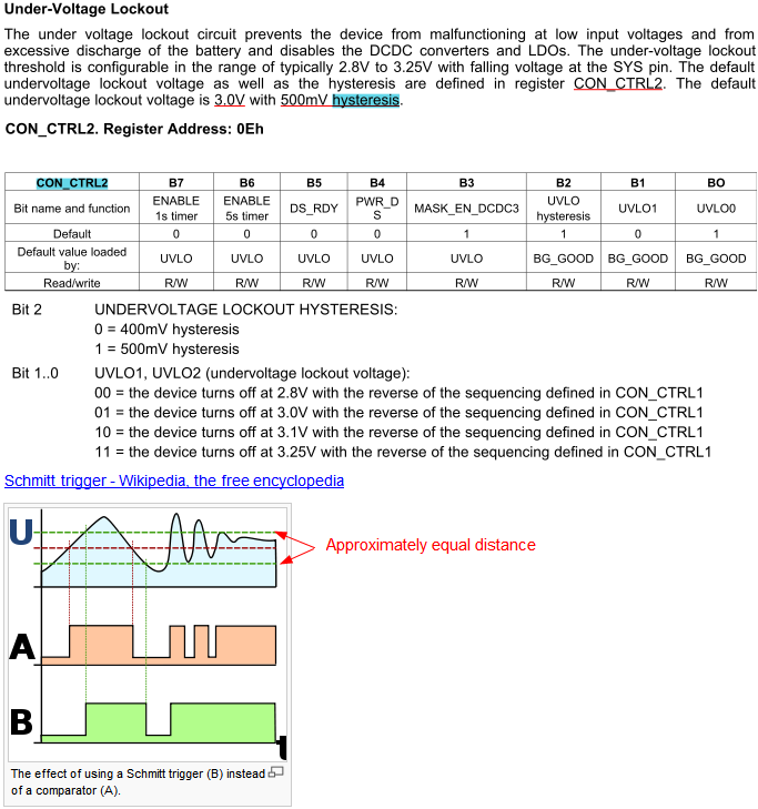
I have little knowledge on Schmitt trigger, but I see on the Wikipedia page illustration that the green lines are approximately of equal distance from the red center line, so I suspect whether it is the same for UVLO hysteresis?


Another question is that is UVLO hysteresis implemented using Schmitt trigger? It seems that there can be a variety of ways for implementing it above at the elemental device (i.e., Schmitt trigger) level, such as maintaining internal registers values and doing comparison. What is the actual UVLO hysteresis implementation?


Zheng

  • Undervoltage lockout will shut the device off when the input goes below Vuvlo, 3.0 V for example. 

    If you set the hysteresis to 500mV, the device will not turn back on until the input goes above 3.5 V ( Vuvlo + Vhyst ).

    UVLO is to prevent the device from repeatedly turning on and off (oscillating) due to the input voltage rising when the load is removed and falling when the load is applied.

    UVLO is implemented with a Schmitt Trigger (or equivalent circuit) as visible in Figure 25. Charger Block Diagram on page 24 of the datasheet.

  • Anonymous
    0 Anonymous in reply to Daniel Acevedo

    Daniel,

    I got your answer.

    So in the Wikipedia illustration above: UVLO is the bottom green line, and hysteresis is the distance between the bottom and the top green line?


    Zheng