This thread has been locked.

If you have a related question, please click the "Ask a related question" button in the top right corner. The newly created question will be automatically linked to this question.

TPS25810: Recommendation for Charging a USB Host Device at 5V/1.5A USB without SW Configuration (using bootstraps)

Part Number: TPS25810
Other Parts Discussed in Thread: TPS25751, TUSB422

Tool/software:

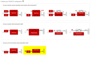
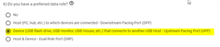
Hello, I'm designing a host port, a UFP in terms of data, and would like to charge the connected host device (the DFP) at 1.5A and 5V, but without configuring a controller with SPI or I2C (using set or bootstrap resistors is highly preferable for this application).

I found this part TPS25810RVCT, that allows setting the current limit to 1.5A using CHG & CHG_HI pins pulled low and high to VBUS, and it says it supports dual role USB3.1 and BC1.2 in conjunction with other parts, but also says it is for charging UFP's only?

Can you advise what I need to verify to ensure this part will work in 3.1 PD mode to charge a DFP host device? If there are too many unknowns, can you recommend an alternate part that will for certain work to charge a host device, configurable with bootstrap resistors? Thank you 

  • Hello, 

    Thank you for reaching out happy to help. In short, you will need to use a USB PD controller. Reason being is that with standard USB Type-C, the data role and power role are fixed to one another. That is why the TPS25810 mentions powering a Sink/UFP device. USB Power delivery allows for the data role and power role to be different through the use of a data role swap or a power role swap. 

    Unfortunately we do not have a resistor configurable device to meet this requirement. The easiest device to implement this will be the TPS25751. This is a DRP USB PD controller that is configured using our easy configuration tool. In the tool, you would select these 2 main fields and that will basically limit the device to 5V and then always initiate a data role swap to become a UFP. 

    Let me know if you have any additional questions after reviewing the device. 

  • Hi Adam, thanks for the information. Since I'm only interested in sourcing power to the upstream data host device, I could use the TPS25751S and not connect any external FET(s) off the gate drive lines (leaving them floating)? I think this is basically what's shown in the bottom right image of the configurator tool you posted? 

    It looks like I either need to program this part every time it powers up over I2C, or connect external EEPROM to tell it to switch to a sourcing role at 5V, 1.5A limit. Assuming, since external EEPROM is required, there is only internal volatile, and so no way to get these parts preprogrammed or configured from the line?

    The options in the configurator only show 5V/3A, but assuming this controller can communicate 1.5A availability with 22k Rp on the CC lines?

    Thank you

  • Since I'm only interested in sourcing power to the upstream data host device, I could use the TPS25751S and not connect any external FET(s) off the gate drive lines (leaving them floating)?

    Yes this is correct and would be my recommendation. That block diagram I highlighted in the above picture is essentially your use case. 

    It looks like I either need to program this part every time it powers up over I2C, or connect external EEPROM to tell it to switch to a sourcing role at 5V, 1.5A limit. Assuming, since external EEPROM is required, there is only internal volatile, and so no way to get these parts preprogrammed or configured from the line?

    Yes your understanding is correct. The image you generate from the configuration tool will need to be loaded onto the PD controller after every power cycle either through a dedicated EEPROM or an external MCU. Here are two app notes that explain the MCU update or the process of updating the EEPROM image in the field if that is something you require. 

    https://www.ti.com/lit/pdf/slvafv8 

    https://www.ti.com/lit/pdf/slvafl1 

    The options in the configurator only show 5V/3A, but assuming this controller can communicate 1.5A availability with 22k Rp on the CC lines?

    Yes this can be done in the GUI. The questionnaire can help set an initial configuration for the device. You can then enter into the advanced configuration allowing for more control of the device. All of these registers are outlined in the host interface technical reference manual


  • Hi Adam, I have also found this part TUSB422, which seems to allow dual role sourcing from our port to a data host, and also requires I2C configuration from an MCU, but has no integrated load switch or FET gate control.

    It seems like this could be a more cost effective solution, used along with a separate load switch for current limiting. Would you be able to comment on the differences between this and the TPS25751S, or any caveats to be aware of (any reason this part would not work)? Thanks!

  • For the TUSB422, in addition to controlling the external power path, you would have to write all of the firmware needed to negotiate a USB PD contract and initiate a power role swap. The TPS25751S would handle all of this automatically without the need for writing firmware for an MCU. Think of the TUSB422 as an I2C to CC converter. 

  • I see, so both need to be configured on start up, just that the more expensive part has a GUI to create the configuration for you in a simplified manner, and also has the option to load register config from EEPROM in addition to I2C. 

  • That is correct.