Tool/software:
Hello,
How can I manage a multiple power supply charger of 21V or 24V with the same BG24610 configuration ?
Th target is have the same battery recharge time whatever charger.
Regards.
This thread has been locked.
If you have a related question, please click the "Ask a related question" button in the top right corner. The newly created question will be automatically linked to this question.
Tool/software:
Hello,
How can I manage a multiple power supply charger of 21V or 24V with the same BG24610 configuration ?
Th target is have the same battery recharge time whatever charger.
Regards.
Hello Guy,
I'm confused on your questions. Are you asking if you can use different input adapters with varying voltages between 21V-24V?
Best Regards,
Christian.
Hello Christian,
Yes , I will have same charge time with input adaptor of 21V or 24V voltages.
Regards.
Hello Guy,
There should be no changes need to support both a 21V and 24V adapter.
Best Regards,
Christian
That's what I thought but in reality charging times are much longer with a 24V adapter.
Charging current ICSET is set at 1.5A but with 24V adaptor , it does not exceed 700mA. Whereas with 21V adaptor , it reaches 1.5A.

Regards.Hello Guy,
Can you provide your schematic?
What is the voltage on ISET1 in both cases?
Best Regards,
Christian
Hello Guy,
What is the voltge on ISET1 in both cases?
Best Regards,
Christian.
Hello Guy,
Can you measure the voltage on the ISET1 and Vref pin in both cases?
Best Regards,
christian
Hello Christian,
Sorry I was in vaccation end of last week.
I'll check voltages tomorrow.
Best Regards.
Hello Christian,
Measurements have been done this morning. All votages are same in both cases.
21V => Vref=3,236V and VISET1=248mV VISET2=251mV VACSET= 550mV
21V => Vref=3,233V and VISET1=248mV VISET2=251mV VACSET= 549mV
Best regards.
Hello Guy,
I see no obvious issue that would cause this behavior, have you tried applying a load the system load? Can you confirm that there is not an issue with the adpater?
Best Regards,
Christian
Hello Christian,
I confirm there is no issue with the adaptator.
We noticed a slight improvement by increasing the value of capacitor between SRN and SRP pins.
C13 : 100nF => 400nF.
What is the job of this capacitor and Could you confirm that this modification can be done .
Best Regards
Hello Guy,
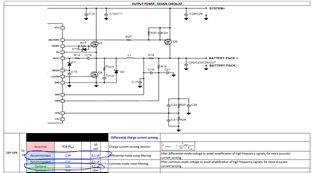
The capacitor is used for to filter differential-mode voltage to avoid amplification of high frequency signals, for more accurate current sensing.
Yes, i see no obvious issue with increasing this capacitor.
Best Regards,
Christian.
Hello Christian,
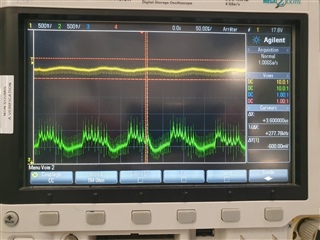
I share you the SRP signal with 24V adaptor.
Green colour is SRP signal with C13=100nF
and Yellow color is SRP Signal with C13=400nF.
As you can see we have low noise with C13=400nF, but it's not perfect. Charging current is around 1.3A instead of 1.5A.
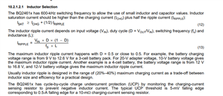
My question is : Do you have an abacus or a formula to calculate the value of L1 inductor ? Perhaps this inductor have an effect depending adaptor voltage ?

Best regards.
Hello Guy,
Please refer to section 10.2.1.2.1 Inductor Selection in the datasheet for choosting the right inductor:

It may also be beneficial to include these caps in your design to improve current sensing.

Best Regards,
Christian.