This thread has been locked.

If you have a related question, please click the "Ask a related question" button in the top right corner. The newly created question will be automatically linked to this question.

BQ25798: Power management between PMID, System load and Battery

Part Number: BQ25798

Tool/software:

Hello TI team,

I’m working on a power supply concept utilizing the BQ25798 and have some questions regarding the IC’s capabilities.

In my design, there are three distinct power sources: a 12V or 24V DC adapter from the grid or PV panel, and an internal 2S2P battery pack.

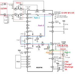
As shown in the attached image, there are four power paths that I need to manage with the following priority:

  1. When a valid source is available on the VBUS input, Path 1 should be active.
  2. If battery charging is needed, Path 2 should activate in parallel with Path 1.
  3. When no valid source is present on VBUS, both Path 3 and Path 4 should be active.
  4. Path 4 should be switchable (ON/OFF) over extended periods to maximize battery autonomy.

Could you confirm if this concept is feasible with the BQ25798, or suggest any adjustments if needed?

Thank you for your assistance with this.

  • Hi ATI,

    Regarding 1, yes, VBUS=PMID when a valid voltage is applied to VBUS.

    Regarding 2, yes, the converter turns on automatically to provide a voltage at SYS and charge the battery unless the host disables the converter (EN_HIZ=1) or charging (EN_CHG=0 or /CE bit = high).

    Regarding 3, path 4 is essentially always active due to supplement mode (when SYS load needs more current than converter can provide from VBUS).  Path 3 is only available if back up mode is enabled.  Backup mode is auto, fast turn on OTG mode where the battery provides a regulated voltage back to PMID (as opposed to VBUS for regular OTG mode) when it senses that the VBUS voltages drops below a % of VINDPM setting.

    Regarding 4, unfortunately, the host cannot disable path 4 even with the external shipFET, as shown above, unless VBUS is removed and the host writes the charger into ship mode or shutdown mode.  In ship mode, I2C registers are still active.  Reapplying VBUS or /QON press auto exits ship and shutdown modes.  In theory (meaning we have not fully tested but a few customers reportedly have), you could add a series resistor from SDRV to shipFET gate and a resistor from shipFET gate to drain of the NFET with source to GND.  The NFET gate can be controlled by host GPIO to collapse the SDRV voltage so that shipFET does not turn on.

    Regards,

    Jeff