Tool/software:
Hi team,
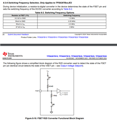
Could you help share the structure and principle of VSET pin circuit? The customers are curious whether there is some filter circuit in the VSET circuit structure. Because they are worried that if they use I2C version and non-I2C version with one schematic design, there will be some noise on the VSET pin. So they want to know the internal structure of VSET pin.
And as far as I know, usually the internal circuit of such design working principle is to sample the current of VSET, then decide the output voltage. So the output voltage is usually decided when start-up. Is TPS6287B25 also working in the same logic? And if so, is its output voltage also decided when start-up? after the output voltage is stable, will the output voltage be changed by VSET resistor in non-I2C version?