This thread has been locked.

If you have a related question, please click the "Ask a related question" button in the top right corner. The newly created question will be automatically linked to this question.

Unstable Charging Current while Powering a the System

Part Number: BQ24074EVM
Other Parts Discussed in Thread: BQ24074, , BQ25616

Tool/software:

Hello!

I am currently building a device that controls 2x12V fans. It is powered by a 3.7 Lipo. I am using the BQ24074 to charge and run the fans at the same time. Charging only works fine. I can also run the system with the battery.  But charging and running at the same time seems to cause some problems.

My configuration:

BQ24074EVM, ILIM mode, JMP term = float, JMP TMR = GND

R_LIM= 1104 Ω -> I_LIM = 1.46 A

R_SET = 1003 Ω -> I_SET = 0.887 A

Lipo: 1S , 3.7 V, 0.150 Ohm, maximum charge capacity 1000 mAh

My system (DC booster, fan, microcontroller) consumes 0.87 A at 5.2 V

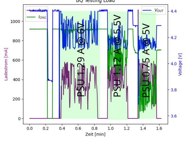
In the following picture you can see V_OUT, I_OUT, I_CHG (charging current measured via testpoint 16 as recommended).


Problem: When the BQ24074 is charged and powered at the same time I_out is very unstable and not even close to I_SET = 877mA. My first idea was that it has something to do with the boost converter. I put some capacitors right after the output (as suggested here: e2e.ti.com/.../5077750, but that didn't change anything.

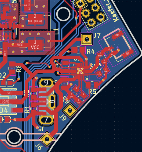
To get a complete picture of my system, this is my schematic (i didnt put the MIcrorontroller on the schematic to keep it "simple". But there is a Attiny44 at V_LOAD as well):


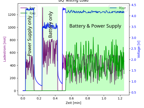
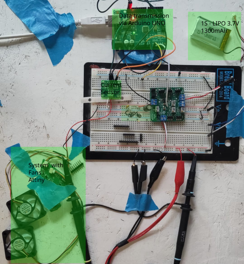
My test setup looks like this:

I have several questions about this:

Is there any way to get a stable charging current of ~900mA while powering the system?

Is this behavior normal? Could it damage anything or shorten the life of the board?

If the problem is the boost converter and the problem cannot be solved with this IC, is there an alternative to supply 12V to the fans?

Thank you very much!

Best,

Chris

  • Hi Chris, 

    The BQ24074 is a 1.5A rated charger. Based off your description the device is not able to support 877mA charging and 0.87A load at OUT at the same time as the desired output current draw is higher than the input current limit. Charge current will be reduced in an effort to power the system load.  

    To achieve stable charging at the same time as powering the system total current draw between system output and battery charging must be roughly less than input current limit. 

    If the problem is the boost converter and the problem cannot be solved with this IC, is there an alternative to supply 12V to the fans?

    You may need to consider a buck type charger IC with higher current rating. Some options include BQ2562x device family or BQ25616 if you prefer a standalone charger compared to an I2C controlled charger. 

    Best Regards,

    Garrett

  • Thank you! I am very sorry my discription was not precise.

    My system (DC booster, fan, microcontroller) consumes 0.87 A at 5.2 V

    My powersupply shows 0.87 @ 5.2V while powering the system AND CHARGING. Furtunately your answer gave me the idea for more testing:

    In this plot you see charging&powering at the same time (green areas) at different supply voltages. I read the voltage values directly from my power supply unit. At 6 V everything works normal. At lower voltages it seems that the BQ is not drawing enough current.

    Is it somehow possible to draw more current at 5V? (I want to use it with a common USB-Type C 3A Charger.)

    If i would use the set up as it is would it be somehow damage the Lipo or the Charger? Is this normal behaviour or should i avoid unstable charging?

    Best,

    Chris

  • Hi Chris, 

    Thank you for the clarification. My mistake for interpreting your comment as 0.87A current draw from the output of the charger IC. 

    At 6 V everything works normal. At lower voltages it seems that the BQ is not drawing enough current.

    Everything working normal with higher input voltage is helpful information. Given the picture of the setup you provided I am wondering if there is some voltage drop between your power supply and the input to the BQ24074 due to small gauge wires and breadboard. If that voltage drop is large enough (5V to ~4.5V) it will lead the device to enter input DPM mode operation and charger IC current draw is automatically reduced. VIN-DPM mode is described in datasheet section 9.3.4.1.1. 

    The device is expected to be able to draw same current with 5V input as 6V input. If possible can you attempt to measure input voltage as close as possible to IC? The lower current draw you observe may be due to test setup.

    Best Regards,

    Garrett 

  • Hi Garrett,

    thank you soooo much! It tested some thicker cables between PSU and EVM and the current draw got better. Even though I am still not drawing 1.3 A @ 5V,  i think you solved the riddle:) I will order some PCB with proper traces and connectors. Hopefully this will do the trick.

    One last question:)

    If the current supply for the BQ24074 is to low for charging and powering at the same time (see last plot above), will it be safe to use the BQ? In other words: Will it decrease the lifespan of the IC?

    Best Regards,

    Chris

    PS: I will mark this thread as solved when i tested the new PCB. Thanks a lot for your quick, precise  & nice help!

  • Hi Chris, 

    If the current supply for the BQ24074 is to low for charging and powering at the same time (see last plot above), will it be safe to use the BQ? In other words: Will it decrease the lifespan of the IC?

    There is no concern from the perspective of the BQ24074 regarding if input source cannot supply sufficient current for both charging and powering system output. Modes such as VIN-DPM, DPPM, and battery supplement mode all exist to allow the device to respond accordingly to this scenario. 

    There is a note below recommended operating conditions section of the datasheet on page 10 which addresses use case where lifespan of IC will be reduced. 

    Best Regards,

    Garrett

  • Hey Garrett,

    I ordered a PCB to see if poper traces will resolve my issue. It is working pretty well. I hace 2 more question to be sure everything is working properly.

    In the picture you see the I_chg is "swinging" around the expected 0.9. During the Fast-Charge the Peak to Peak Amplitude gets bigger. Fast-Chrarging goes till 14:19.

    Question 1: Is the increasing swinging behaviour normal?

    Here you see the 2-Layer PCB Design. I have tried to orientate myself on the layout of the Data Sheet.

    Question2: As the circuit board gets quite hot, do you see any possibilities to improve the heat conduction? Would e.g a 4 Layer Design with 2 extra GND-planes help? Or do you see any other possibilities?

    Best Chris

  • Hi Chris, 

    Great to hear the IC overall appears to be working well on your PCB. Please see my comments below.

    Question 1: Is the increasing swinging behaviour normal?

    The BQ24074 reaching thermal regulation due to high IC temperature or fast transients on system load connected at OUT pin are two possible explanations for the observed charge current oscillations.

    If there was a fixed OUT pin current draw and IC is operating below thermal regulation temperature threshold (125 deg C) I would expect charge current to remain stable near the 0.9A set point. 

    Looking back at the plot you previously provided I see IOUT is changing throughout operation. Given this some ICHG oscillation is normal.

    Question2: As the circuit board gets quite hot, do you see any possibilities to improve the heat conduction? Would e.g a 4 Layer Design with 2 extra GND-planes help? Or do you see any other possibilities?

    Yes a 4 layer board with additional GND plane is expected to help with heat dissipation. 

    Best Regards,

    Garrett 

  • Nice, great support!

    Best Regards, 

    Chris