This thread has been locked.

If you have a related question, please click the "Ask a related question" button in the top right corner. The newly created question will be automatically linked to this question.

TPS55288: Unable to get to full power (~6A)

Part Number: TPS55288

Tool/software:

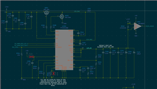
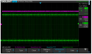
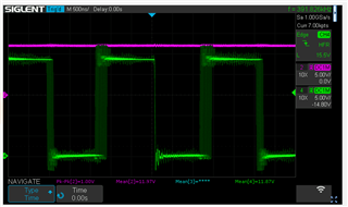
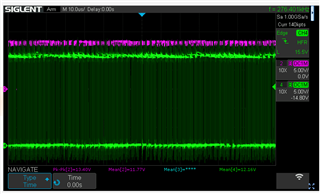
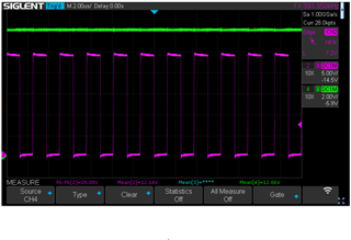
I went to the Webench for a design (attached) that would allow me to have 22-24Vin, 12-16Vout, Imax 6A. After implementing the design I'm noticing that Vout looks good up until ~3.2-3.5A. At that point I get a rapidly increasing ripple and then voltage drops to 0V. Checking the status register doesn't seem to show any errors. Possibly the part is resetting before I can query that though. Inductor temp is a fairly reasonable 45C. Vin looks stable all the way through. Any suggestions of where to look for issues?

TPS55288_Regulator_WebBench.pdf

  • Hi Simon,

    Thank you for reaching out. May I know what is the application here?

    Did you design a PCB by yourself? If so , can you share your schematic to me?

    What is the input and output voltage when voltage drop to zero? Can you share waveforms of SW1,SW2,Vout, inductor current when the phenomenon happens?

    Regards,

    Mulin

  • Hello Mulin,

    Yes, this is part of a larger PCB. Application is to drive 4 small audio amps (LM4950s) that are used as the power stage for a tone generator. 

    Notes on the SCH below. I added an additional 22 uF on top of C332 to bring my total up to 3. I added a 1uF right at the Vout pin as well

    Notes on images below: SW1 is Green, SW2 is Purple. Operating exclusively in buck mode. Vin is stable the whole time. 

    Image 1 is under no load.

    Image 2 in under 1.5A load, I notice the ringing is higher

    Image 3 is under 2.5A load, lots of ringing and I being to see jitter in SW1.

    Image 4 is under 3A Load, More jitter than stable switching

    Image 5 is under 3A load, same as Image 4, just zoomed out. Shortly after this point the switching stops and output drops to zero. Removing the load allows the regulator to recover and come back up to 12Vout.

  • Hi Simon,

    It looks like a loop stability issue. Please change R314 to 10k and L303 to 4.7uH to see if it is better.

    Regards,

    Mulin

  • I have ordered the parts to make those changes and retest. What is the thought behind changing the COMP resistor so much? I'm not sure how that portion works.

  • Hi Simon,

    Because 178k is too large for this IC. This will cause very high cross frequency. Phase margin and gain margin will be low. Webench parameters are for reference and we need to adjust according to real application. Change to 10k will be a common-used value. But it may still need some adjustment accordingly. We can wait for the result first.

    Regards,

    Mulin

  • This resolved the issue, I now have full design power. Just to close out for anyone later on finding the thread. Here are the followup traces of SW1 after the compensation resistor change. 187k to 10k. I also did the inductor change just for completion but the major effect seemed to be this resistor.

  • Hi Simon,

    Glad to hear that. Recommend to  use 4.7uH inductor for better transient performance. I will close this thread. If you have more questions, feel free to reply and it will open again.

    Regards,

    Mulin