This thread has been locked.

If you have a related question, please click the "Ask a related question" button in the top right corner. The newly created question will be automatically linked to this question.

LM5155: PGOOD pin current rating

Guru 12065 points
Part Number: LM5155

Tool/software:

Hi,

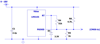
Could you please let me know if there is any information on the LM5155 PGOOD pin current rating? The datasheet states that "When VPGOOD > VBIAS, the maximum current sink is limited to 1mA," but this means that the current sink is limited to 1mA when the PGOOD pin is active. As I understand it, this is different from the absolute rating.

The background to the question is that with the current design, there is a possibility that about 5mA may flow to the PGOOD pin, and I would like to know if this will be a problem.

Thanks,

Conor

  • Hi Conor,

    Thanks for reaching out.

    Please give me some time to look into this.

    I will come back to you until the end of the week.

    Best regards

    Moritz

  • Hi Moritz,

    Can you respond by today? I look forward to hearing from you.

    Thanks,

    Conor

  • Hi Conor,

    PGOOD will sink 5mA when PG is pulled low or not?

    Can you show a diagram? I am not sure if I understand you well.

    Best Regards,

    Feng

  • Hi Feng,

    Sorry, I don't have the circuit diagram on hand, so I need to check with the customer.
    However, what the customer wants to know is information about the rated current of the PGOOD terminal. It seems that the current design may allow about 5 mA to flow through PGOOD.

    Thanks,

    Conor

  • Hi Conor,

    Please check what is the case for the customer.

    Best Regards,

    Feng

  • Hi Feng,

    I'll share the circuit diagram around PGOOD. I look forward to your comments.

    Thanks,

    Conor

  • Hi Conor,

    In this case, PGOOD is always less than Vbias.

    PGOOD will sink 18V/4.7k=3.8mA when PGOOD pulls low. I believe this is still acceptable in this case.

    But I am confused about RT configuration, can you tell me what is the purpose of this configuration?

    Best Regards,

    Feng

  • Hi Feng,

    The customer is considering a method to activate PGOOD (Hi-Z state) when an abnormality is detected (FB pin voltage exceeds VUVTH) to reduce the current flowing out of the RT pin and lower the switching frequency (stop the gate output).

    During steady-state operation, the RT pin is shorted to AGND, so I don't think there will be any problems, but I am wondering if there are any times when the PGOOD pin will become Hi-Z in any sequence other than the FB pin voltage. Also, are there any concerns that this type of usage will cause problems?

    Thanks,

    Conor

  • Hi Conor,

    This is not a typically application and I cannot predict the behavior of the device under this condition.

    Best Regards,

    Feng

  • Hi Feng,

    Okay, I will do a thorough check, but I have one question. The datasheet says that in order for the PGOOD pin to go to Hi-Z, the following conditions must all be met:
    -FB pin voltage > feedback undervoltage threshold (VUVTH)
    -VCC pin voltage > VCC UVLO threshold
    -UVLO/EN pin voltage > EN threshold

    Does the PGOOD pin go to Hi-Z only when the above three conditions are met? I'd like to know if there are any other times or conditions when the PGOOD pin goes to Hi-Z.

    Thanks,

    Conor

  • Hi Conor,

    Please create a new thread for this topic.

    Best Regards,

    Feng