This thread has been locked.

If you have a related question, please click the "Ask a related question" button in the top right corner. The newly created question will be automatically linked to this question.

TPS25750: Need to Charge Two 4S Batteries as Parallel Circuit Needed Suggestion

Part Number: TPS25750
Other Parts Discussed in Thread: BQ25798, TIDA-050047, TPS25751, TPS65988, BQ25756

Tool/software:

Hi TI Team,

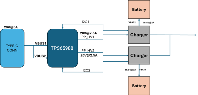
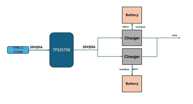
 I am working on a Project where i needed Two 4s Batteries to be used based on Higher Load Requirement using Type-C Power.

Can i use TPS25750 as a PD Controller & BQ25798 as Battery Charger for my above Application. As my Battery charges at a Rate of 16.8V @ 3A. Can you please suggest if I can use the following IC's or need to go for any Alternate parts

Block Diagram is attached for your Reference.

Immediate Response would be Highly Appreciable. 

  • 1) Needed Clarification on Interfacing the PD Controller I2C to both the battery Chargers I2C & also need to provide the Information to Processor for Battery Indication.
    2) Whether we need to provide Two "Aardvark Header" for programming for both the Charger IC's & how about EEPROM for Register Storage. Request to provide the Guidelines for Programming. 
    3) Whether these IC's are pre Programmed Devices (Plug & Play ) or need to program for every Device. 
    Note: 
    As per the Reference with the User Manual for TIDA-050047.
    Master I2C Interface from PD Controller will be interfaced with Charger IC & EEPROM & Aardvark Header & in GUI, The Device details are provided for selecting the Voltage & current Levels.
    In the above mentioned Application can you please suggest how I am able to interface the Devices & Program the same.
  • Hi, 

    Thank you for reaching out!

    1- The PD controller can only control one battery charger over I2C. You may need to consider two PD controller for your application. I would also like to highlight our follow-on device, the TPS25751, recommended for all new designs. Please see the following FAQ for more information. 

    2- The aardvark header is used to program the PD controller's external memory (EEPROM). 

    3- The IC's would need to be flashed with a configuration fit to your application needs. We have an easy-to-use GUI tool that generates a binary file by just answering a few questions. This binary file would then be used to flash the EEPROM via an aardvark. 

    I will loop in a battery charger expert to help with part selection here. 

    Best Regards, 

    Aya Khedr 

  • Hi Aya Khedr,

     Thanks for the immediate Response,

     As per the above points mentioned by You regarding Two PD Controllers for my Application.

     Can I use "TPS65988" part which is a Dual Type-C PD Controller for my Application for Charging Two Battery Charger Circuits.

    In my Application, I want to use Single USB Type-C Connector as a Single Input for 20V@5A Supply. Please find the attached Picture for your Reference & Request to provide the update on the same

    Can i able to limit my Input VBUS current. So that i can give equal current of 20V@2.5A for each VBUS Input supply.

    .

    As this Device have Two I2C Controls can i use individual control to individual Charger IC.

    Do we have to Program this Device using any specific GUI for controlling both my charger IC's using PD Controller. In this case whether I need to use Two EEPROM or Single would be sufficient.

    If I can use this Device for my Application can you please provide an Evaluation Board for the same. SO that it would be much Helpful

  • Hi,

    The BQ25798's SYS pins cannot be directly tied together.  You will need a (ideal) diode OR.

    Regards,

    Jeff

  • Hi,

    can you change the 2 separate 4S battery packs to 1 larger battery pack or 1 8S battery pack and use the BQ25756 for higher power charging instead?

    Regards,

    Jeff

  • Hi, 

    The TPS65988 is a dual-port USB PD controller that is paired with two Type-C connectors (see diagram below). This device does not have integrated I2C control for battery chargers. 

    For your application, if possible, I recommend looking into the pairing of the TPS25751 (up to 100W input) + BQ25756 (up to 16s battery charging) See the following reference design for an example. The TPS25751 has integrated I2C control for the BQ25756, reducing much of the complexity associated with the pairing of both devices. 

    Best Regards, 

    Aya Khedr 

  • As per my Application requirement I can go with a 4S Battery Only that If i need to go for a Single Pack we are having some Conflicts with respect to our Application with respect to Dimension & Charging Time. So that's the reason we had to go for Two 4S Battery Packs

  • As per Datasheet mentioned I think TPS65988 can be used as both Source & Sink. Please find the below attached pictures & also this IC supports around 3 I2C Interfaces.


    Request to verify & suggest if I can use this Device. 

    If I need to go for TPS25751 & BQ25756 Combination, I think I need to use two PD Controller Devices.

    Can I use TPS65988 & BQ25756 Combination is it possible.

  • Hi, 

    I would still recommend 2 x TPS25751 as it is more cost effective than 1 x TPS65988. There are also additional benefits to the TPS25751 such as the integrated I2C control for BQ, liquid detection, easy-to-use GUI tool.  

    Best Regards, 

    Aya Khedr

  • The above Solution Resolves most of my issue thank you for your kind suggestion.

    A Small Suggestion required. Not sure if this approach is suitable or not.

    If I use a Single Type-C PD Controller with Single charger & the output of Charger if I connect to a Dual Output Power Switch.

    The Charger IC STAT Pin controls the Power Switch for Switching between two Batteries while Charging.

    So that First Battery charges First the STAT pin of Charger will be Low while charging & Once Battery is charged to 100% then the STAT Pin switch from Low to High. Then the Power Switch stops charging BAT1 & initiates connectivity with Secondary Battery & starts charging the Same.

    Even the I2C Interface from charger to Battery BMS will also be shifted between two Batteries using I2C Mux where the Multiplexer will be controlled by STAT Pin of Charger IC.

    Can you please suggest if I can use this Option for my Application. SO that it reduces most of my BOM & Design complexity.