This thread has been locked.

If you have a related question, please click the "Ask a related question" button in the top right corner. The newly created question will be automatically linked to this question.

TPS2491: Designing a Current Limit Circuit for a 48V Battery-Powered Motor Driver

Part Number: TPS2491
Other Parts Discussed in Thread: TPS1685,

Tool/software:

Hi E2E

I’m working on designing a current limit circuit for the schematic below and would appreciate advice on selecting the optimal IC and circuit for this application.

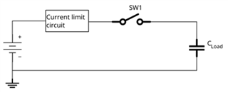
The power source is a 48V battery capable of delivering hundreds of amps, with the load consisting of a motor driver and other high-capacitance equipment.
To avoid the battery’s BMS from shutting off due to inrush current, the current limiter must effectively control inrush when SW1 closes.
Notably, SW1 can be activated at any time. The design of the application prevents me from changing the order of the current-limit circuit and SW1.  


Application Requirements

  • Battery Voltage Range (VBat): 42V – 57V
  • Maximum Load Current: 20A
  • Inrush Current Limit (BMS): 100A for 1ms
  • Maximum Capacitive Load: 10,000 µF
  • Maximum in-rush char time: 1sec


I've been evaluating the TPS249x series of hot-swap controllers for this purpose. However, I’m uncertain if it’s the ideal choice for this circuit. Since the current limiter is always connected to the battery, it remains active even when SW1 is open. When SW1 closes, the current limiter wouldn’t engage in a startup sequence but may shut down due to the high inrush current.

I’d appreciate any advice on whether the TPS249x series is the best fit here, or if there might be a more suitable approach using a different technique than hot swap controllers.


Thank you in advance for your recommendations and ideas.

Best regards,
Sam

  • Hello Sam,

    You can use the TPS249x FET as SW1 in your schematic.

    You can check TPS1685 for your application. It has integrated FET for high side FET for high voltage application.

    You can also easily stack them for effective current sharing. Let me know your thoughts on TPS1685 and TPS249x.

    Thanks 

    Amrit 

  • Hi Amrit,

    Thank you for your suggestions!
    Maybe I was a bit unclear about SW1. The switch is a electromagnetic emergency stop contactor in the system. I cannot exchange this part with a FET based.
    The current limiter must react on the opening and closing of the SW1.
    My concerns about using TPS249x is that in this setup its not really hot swapping, as it is always active as it is connected directly to the battery and therefore always enabled.
    When SW1 is closed I believe the following will happen:
    1. The Vout of the TPS249x will suddenly drop.
    2. TPS249x will see this turn off the FET as described in section 7.4.4 of the datasheet.
    3. If TP2491 is used, it will make a start-up sequence after a reset time.

    I find it a bit counter intuitive that the current limiter always disconnect every time SW1 is closed. I was wondering if there were any other way to solve this issue.

    The TPS1685 look very promising. Do you have any knowledge when it will be in production?

    Best regards,
    Sam.

  • Hi Amrit,

    A follow up question regarding the hot swap controller or other IC´s.
    Is there any IC with two different current limts; One during startup and one when the FET is fully on?
    In this application, I would like to charge up the capasitors with a smaller current, lets say 1A, but allow 20A once the startup sequence is over. 
    The charging time in this application can be up to 1 sec. 

    Best regards,
    Sam

  • Hello Soren,

    We use dVdT start-up for charging the capacitor. Device turn on slowly allowing to charge the cap.

    We have the current limit only during steady state opeartion.

    Thanks 

    Amrit 

  • Hi Amrit,

    Of course, that makes sense. Thank you.
    Is there a clever way of quickly charging the gate if the capacitance is not as high as expected?
    Let say that I configure the dVdt rate to charge up a capacitance 500uF in one 1sec.( just an example)
    If the capacitance instead is 250uF, it will be charge quicker, but the charging of the external gate capacitance(C_dVdt) will still be charging up the gate.  I guess this will result in that the MOSFET is still in dv/dt mode even though the voltage has been charge to Vin. Is that correct?
    Is there are a cleaver circuit that will "stop" the dVdt mode once the output capacitance has been charge?

    Best regards,
    Soren

  • Hello Soren,

    Is there any potential risk in your circuit with slower output ramp?

    I will suggest you check with TPS2491 design calculator.

    Thanks 
    Amrit 

  • Hi Armit,

    There is no risk. The only thing is that the rest of the application have to wait for that 1 sec, before high power can be drawn.

    Best regards,
    Soren

  • Hello Soren,

    It won't be 1 sec. Using dVdT cap will help with reducing the inrush current and protect the external MOSFET .