Because of the Thanksgiving holiday in the U.S., TI E2E™ design support forum responses may be delayed from November 25 through December 2. Thank you for your patience.

TPS61377: Switch on/off Hysteresis

Part Number: TPS61377

Tool/software:

Hello,

I have replaced the resistor R8 with 220 k and R9 with 22k on the EVM. The measured switch on/off thresholds are:

Switch on

8.891 V

Switch off

8.386 V

Hysteresis

0.505 V

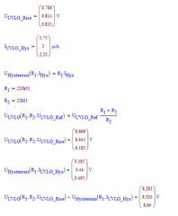
Using the formula in the data sheet, I expected the following threshold values. The on/off thresholds are OK, but the hysteresis is too high.

I have measured similar values on our assemblies. Can you please check whether my calculation approach is right.
Best regards,

Alexander

  • Hi Alexander,

    I see no concerns on your calculation.

    If you need smaller hysteresis, you may just make the R8 (R1 in your calculation) smaller.

    Regards

    Lei

  • Hello Lei,

    thanks for the quick reply. The resistance tolerances are negligible, is the maximum hysteresis current specified in the data sheet correct.

    Do you have measurements of the hysteresis current.

    Kind regards,

    Alexander

  • Hi Alexander,

    The hysteresis current is tested for every shipped units. The data sheet spec is reliable. 

    Regards

    Lei

  • Hello Lei,

    I wonder, if the hysteresis current is according to data sheet and the calculation method is correct, why is the measured hysteresis out of calculated tolerance?

    Kind regards,

    Alexander

  • Hi Alexander,

    The hysteresis current in datasheet is guaranteed.

    Please double check the actual resistance of the 220kΩ R8. And also please provide the way how the switch on/off voltages are measured.

    Regards

    Lei

  • Hello Lei, 

    I unsoldered the resistor and measured it, the resistance value is 219.8 kOhm, so the resistance value is fine.


    To measure the switching thresholds, a voltage source is applied between J3 and J4 on the EVM .The voltage is increased in 1 mV steps until the controller starts. The voltage is then reduced in 1 mV steps until the controller stops. Switch-on threshold minus switch-off threshold gives the hysteresis.

    Best regards,

    Alexander

  • Hi Alexander,

    Thank you for your detailed information.

    It seems all good for your measurements. Let me double check and get feedback to you tomorrow.

    Regards

    Lei

  • Hi Alexander,

    When you measured the switch on time, what signal you used to judge the device on time?

    And also, what's the rising slew rate of the UVLO voltage?

    I think the soft start time may make the device on time a little confusing.

    Regards

    Lei

  • Hi Lei,

    to find the switching thresholds, I checked the output voltage. The slew rate of the supply voltage was very slow, the supply voltage was increased by hand in approx. 1 mV/s.

    I have made further measurements.

    1) EVM supplied with 13 V and EN/UVLO pin connected to a DC source via 10 kOhm. The voltage across the 10 k resistor was measured with a multimeter.

    The measured hysteresis current of 2.07 uA is within specified value 1.75..2.25 uA.

    DC Source Voltage [V]

    0

    1

    Voltage across 10 k [mV]

    0

    20.7

    Resulting input current [uA]

    0

    2.07

    Rsulting hysteresis voltage [mV]

    -

    455

    2) EN/UVLO connected via resistor devider and switch on/off threshold measured as explained above. Additionall the voltage at EN/UVLO pin measured. It seems that the threshold voltage of the comparator has also changed a little, so that the total hysteresis is higher than expected.

    Switch on threshold @ EN/UVLO pin [mV]

    809

    Switch off threshold @ EN/UVLO pin [mV]

    805

    Switch on/off hysteresis @ EN/UVLO pin [mV]

    4

    Swith on/off hysteresis in relation to supply voltage [mV]

    44

    Regards,

    Alexander

  • Hi Alexander,

    Thanks again for your detailed information.

    For your first measurement, I think the measured 2.07μA hysteresis current is more accurate than the one measured previously. Sorry I didn't know where the gap comes from now.

    It's correct that there is a small hysteresis of the UVLO  threshold.

    Regards

    Lei

  • Lei,

    I am a bit confused, in your last post, you mention a first measurement, but there was no previous measurement.

    Is it correct that besides the hysteresis current according to the datasheet, there is an additional hysteresis voltage on the comparator that is not mentioned in the datasheet?

    Can you specify the hysteresis voltage including tolerences or can you confirm the 0..6 mV additional hysteresis voltage?

    Best regards

  • Hi Franziskus,

    I am a bit confused, in your last post, you mention a first measurement, but there was no previous measurement.

    In my post, the "first measurement" refers to Alexander's measurement shown below. From which the hysteresis current = 0.505V/219.8kOhm = 2.30μA

    The "second measurement" refers to Alexander's measurement shown below. From which the hysteresis current = 2.07μA

    The 2.07μA is in the datasheet spec.

    It's correct that there is a small hysteresis of the UVLO  threshold.

    Sorry I need to correct my post about the hysteresis of the UVLO  threshold. Confirmed with designer, there is no hysteresis.

    Just some more comments for your reference.

    I've also measured the UVLO threshold on EN/UVLO pin with a multimeter. When measured the "Switch off threshold @ EN/UVLO pin [mV]", I just carefully adjust the Vin to make it just 1mV higher than the device switch off voltage(8.466V, in my case). After the multimeter probe touches the EN/UVLO pin, the device was turned off. That means the measurement by multimeter itself makes the voltage on EN/UVLO pin a little smaller. So I wonder whether the 805mV was also a little lower than the actual value caused by the measurement.   

    Regards

    Lei