This thread has been locked.

If you have a related question, please click the "Ask a related question" button in the top right corner. The newly created question will be automatically linked to this question.

UCC2818-EP: UCC2818-EP PFC Input current problem

Part Number: UCC2818-EP
Other Parts Discussed in Thread: UCC28180, PMP31164, UCC25640EVM-020

Tool/software:

Hi TI team

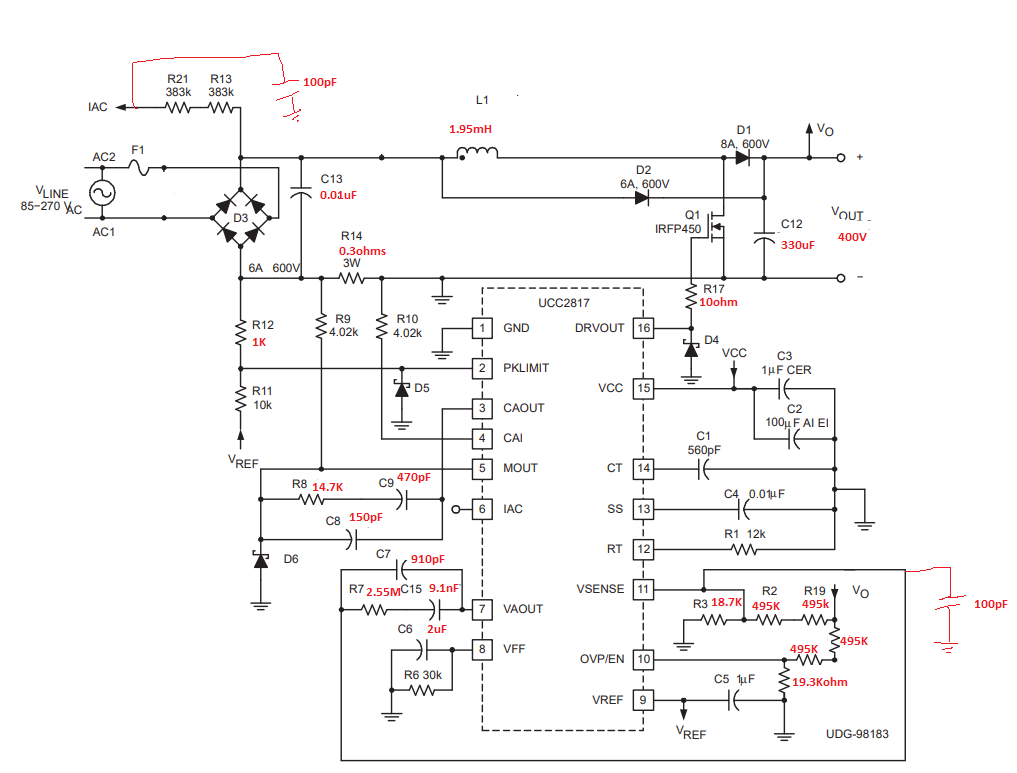
We have build a PFC board using UCC2818-EP PFC IC. 

Following is our requirement

Vin :100Vrms to 134Vrms (360Hz to 800Hz)

Vout : 400V (100W)

Previously we tested UCC28180 IC using Eval board as per PMP31164 reference design following link we had discussed the problem we have faced.

https://e2e.ti.com/support/power-management-group/power-management/f/power-management-forum/1360981/ucc28180evm-573-power-management-forum/5245338?tisearch=e2e-sitesearch&keymatch=%252525252520user%25252525253A604376#5245338

Now we build a PFC board using UCC2818-EP following is the schematic and we are seeing some issues in the input current. Current loop is set to be around cutoff frequency of 20KHz and voltage loop is set to be around 68Hz.  Is it a problem with Compensation? Current is peaking only on positive side of voltage and duty seems to be normal in all the cases, as i increase the load the current also starts peaking more.

  • Hello Ramahadullah, 

    Please allow me a short time to study the issue and I'll reply to you.

    Regards,
    Ulrich

  • Hi Ulrich

    I forgot to mention that RT and CT value is tuned to have 100kHz switching frequency. And the 400V output was loaded with UCC25640EVM-020. 

  • Hi Ramahadullah, 

    I was working on this issue when your post just came in. 

    I do not think that the voltage loop or current-loop compensation values are the cause of this problem.

    I am concerned about the effects of the two 100pF capacitors that are manually added to the schematic in red ink, at IAC and VSENSE pins. 
    I suggest to remove them, one at a time to assess the effects of each. 

    In particular, I suspect the 100pF cap on IAC.  I think it may be affecting the IAC current into the the multiplier and the voltage waveform on the VFF pin. 
    The VFF should have a dc level proportional to the AC rms input with very little ripple voltage on it.  VFF is also an input to the multiplier, whose output is the reference for the current-loop amplifier. 

    If IAC and VFF are distorted by the capacitor, then that can account for the strange one-sided input current. 

    I don't think that the VSENSE capacitor has much effect (if any) on this current waveform, but it is unusual, and it is worth checking to see if it contributes or not.   
    I suggest to remove the VSENSE 100pF cap first.  If the current doesn't change, then remove the IAC cap. 

    Regards,
    Ulrich

  • Hi Ulrich

    Thanks for the suggestion.

    We removed those capacitors which didnt help in solving the issue.

    To find out the source of issue, we used resistive lamp load on the 400V . The input became sinusoidal. The culprit was the secondary side DC-DC LLC converter. 

    But when we connected back the DC-DC converter on the 400V PFC output the problem came back. I think we have period doubling bifurcation due to the secondary converter load. 

    Do you any suggestion to avoid this period doubling phenomena?

    Reseaarch paper in the attached link discuss about this phenomena

     https://ieeexplore.ieee.org/document/1522939

    Thanks

    Regards

    Rahamadullah

  • Hi Ramahadullah, 

    Thank you for finding that paper and providing a link to it. Clearly your system is suffering from the slow-scale period-doubling instability that is investigated in the paper. (Note: Reference [6] in that paper refers to bifurcation period-doubling, but that refers to doubling of the switching period, not of the rectified AC line period. As I read it, your issue does not involve bifurcation.)
    This paper tells me that my doubt about voltage-loop compensation involvement is incorrect. 

    The input current of the PFC is shaped by the UCC2818-EP multiplier output signal, therefore one or more of the inputs to that multiplier must be carrying the slow-scale period-doubling modulation.   The three inputs to the multiplier are IAC, VFF, and VAOUT.  
    IAC is a current, but is derived from the voltage on the output of the bridge rectifier.  As long as that voltage waveform is the same from half-cycle to half-cycle (as is normally expected), then IAC should also be the same each half-cycle of the line.
    VFF is a voltage derived from IAC and should be nearly a DC level with a very small twice-line frequency ripple voltage superimposed on it. 

    Please check and verify that, with the LLC stage attached, the rectified voltage and VFF voltages are as expected ( same as with resistive PFC load). 

    Assuming that those are clean, that leaves the VAOUT waveform to carry the period-doubling modulation. 
    Please check the VAOUT waveform to verify this.  

    The paper discussed the interactions of the PFC control with that of a buck-derived DC-DC converter.  Your experience with an LLC second-stage indicates that the issue is more general (not specific to bucks) but we can suppose that the principles of stability should hold true regardless of DC-DC topology. 
    On the other hand, the stability boundary curves of Figure 6 in the paper may be insufficient given that the LLC feedback loop gain-block may be much more complicated than a simple gain term over a time-constant term.  
    Yet, the curves do suggest that stability can be achieved by adjusting one or more of the gain and/or crossover frequency parameters of either the PFC stage or the LLC stage, or both.

    I think there is a possibility that this problem can be solved by incorporating some damping of low-frequency resonance between the two stages. 
    Here are two papers by Erickson that I found in my files, that discuss adding damping to to improve the phase characteristics of the output and input impedances of two cascades stages.  The papers involve EMI filters interacting with the negative impedance of a buck DC-DC, but I think the concepts can apply to PFC with LLC as well.  
       Optimal_single_resistors_damping_of_input_filters.pdf      EMI Filter Damping.pdf      

    Since damping an LLC converter may prove challenging, I suggest to first try adding R-C damping across the PFC output capacitor.  If that is successful, then try to achieve the same damping using R-L across the boost inductor.  But theoretically, the PFC is supposed to change the inductor effectively into a "current source" so L-R damping may not work.    

    If any kind of damping does not work, then the fall-back plan is to change the gain/crossover characteristics of one or both of the power stages so that the period-doubling of the input current goes away. 

    Regards,
    Ulrich


  • Hi Ulrich

    Thanks for the suggestions.

    We tried the following:

    1. Tried reducing the low frequency gain of  PFC voltage loop it didnt gelp.

    2. Tried reducing the voltage loop crossover it didnt help.

    3. Tried adding an LC filter in between the PFC output and LLC input (L=680uH, C=0.068uF, Rdamp =10ohms, Cdamp=4*0.068uF) It didnt help.

    4. Tried powering on with a different 400V to 12V converter there was no issue with current (it was stable). Current was purely sinusoidal.

    I think we are having problem with LLC converter. 

    Regards

    Rahamadullah

  • Hi Ramahadullah, 

    Did you try adding an R-C damping network across the PFC output cap?  Or increasing Cout by a large factor?  

    After exhausting attempts to adjust the response of the PFC prove fruitless, I agree that the focus should shift to adjusting the LLC control. 

    I am not an expert on LLC.  But I suggest that the same set of changes can be tried on the LLC control loop.  
    -  Change loop gain
    -  Change crossover frequency (either down or up). 
    -  Try running the LLC from a benchtop DC source, if possible, to assess its stability.  

    Regards,
    Ulrich