BQ40Z50-R2: Will welding B -/B1 first and then welding B+every 3 days have an impact on the electricity meter

Part Number: BQ40Z50-R2
Other Parts Discussed in Thread: BQ40Z50, BQSTUDIO

Tool/software:

Hi

When I was using the BQ40z50 battery meter, I found a problem. When welding the battery cells, I first welded B -/B1, then left it for 3 days, and then welded B+. After completing the B+welding, I conducted a semi-finished test on the battery(Charge and discharge test, with current of 6A/2A/1A). During the test, I found that the voltage of B -/B1 cells was 10-20mV lower than that of B1/B+cells. In order to control the voltage difference between the two cells within 8mV, after completing the semi-finished test project, I activated the battery and let it rest to balance the voltage of the two cells on its own. However, after balancing for 1 day, I found that some batteries had a situation where the voltage of cell 2 was 0, and there were approximately 22. A battery with such a situation was analyzed, and it was found that the protection board did not leak electricity. The balancing function of the protection board was also tested without any problems, I am currently very puzzled as to why the voltage of cell 2 is 0. I hope to receive your help. Thank you very much
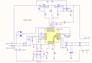
  

  • Hello,

    How are the FETs being controlled in this situation? Is FET_EN being used to give the gauge the control of the FETs?

    Would it be possible to receive a bqStudio log file of the situation while the voltage of cell 2 is decreasing so we can take a look into what is internally happening with the gauge?

    Regards,

    Anthony

  • HI anthony

    Due to the fact that the voltage of cell 2 was already 0 at the time of discovery, it was not recorded in the bqStudio log. I would like to know if this welding method will cause incorrect data or other issues with the battery meter itself

  • Hello,

    If the gauge was able to correctly read the voltage from cell 2 at a point, then I do not believe there is an issue with the way it was soldered to the board. 

    I activated the battery and let it rest to balance the voltage of the two cells on its own. However, after balancing for 1 day, I found that some batteries had a situation where the voltage of cell 2 was 0, and there were approximately 22.

    In this situation, is there any standby current that could be seen that could cause this change? It is difficult to determine what the root cause if this is without a bqStudio log depicting the situation.

    Regards,

    Anthony

  • Hi,

    I received two batteries that had undergone the same operation. One battery cell voltage between B+and B1 did not drop to 0V, while the other voltage dropped to 0V. I captured the log information and found that communication suddenly interrupted during the capture process, which seemed to trigger a shutdown. The voltage of 0v, I understand, is lower than the set shutdown voltage of 2800mv and automatically enters shutdown after 250 seconds. Another reason, I don't know what, please refer to the attached abnormal data_defu. zip for the log. The voltage did not drop to 0v, and bat_2 to 0. zip for the battery cell voltage between B+and B1 dropped to 0v. Can anomalies be found in the log information? And the reason why the voltage of battery cell 2 consumes up to 0V

    abnormal_data_sefu.zip

    bat2_to_0.zip

  • Hi Ian,

    Thank you for sending these files, this is an odd situation because if the cells are well connected, the gauge should disable discharging when the CUV protection is triggered by opening the DSG FET. I believe there is something happening physically where a disconnection is being made because the gauge would normally not allow the cell to become less than the CUV protection.

    Would it be possible to share the layout design of the board in use?

    Regards,

    Anthony