Other Parts Discussed in Thread: LM25185
Tool/software:
Hi there,
I'm design a flyback converter but I'm getting some trouble during PSpice simulation related to compensasion network.
The converter specs are presented below.
Vin: 20~36V, Vout:16V, Pout:42W, VD:0.7, NPS: 1:1, Lm=10uH, Cout:200u, D_Nom = 0.3736, R_Cs = 10mΩ
Compensation design results:
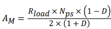 AM = 1.39
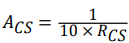 ACS = 10
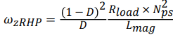 WzRPH=640151.46
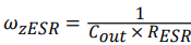 WzESR=1000000
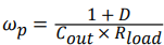 Wp=2253.57
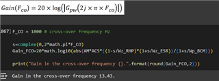
Calculating a Gain in cross-over frequency (F_Co = 1kHz)
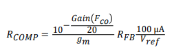
Calculating RCOMP
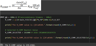 RCOMP = 261kΩ
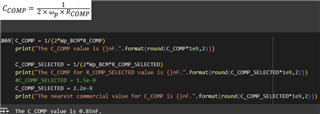 CCOMP = 0.85nF
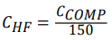 CHF = 5.7pF
Simulating this circuit in PSPICE I got these currents in Lprimary (green) LSec (Red), it seams my compensation network is not working very well.
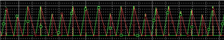
Am I doing something wrong during the compensation design?
Thank you