Tool/software:
I'm trying to create bluetooth beacon with integrated low-power qi/wpc charging circuit and PCB antenna (BQ51013B as wireless receiver, BQ25101Y as battery charger). Batteries will be very small, so charging current will vary from 10mA to 40mA just. My problem is which values use for capacitors calculation. I've measured my PCB antenna (about 20x15mm size) inductance in 4 cases:
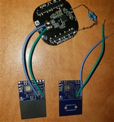
1. Just antenna, without any shielding - 13.7 uH (right on the photo)
2. Antenna with ferrite shielding pad (left on the photo) glued to the PCB by ~0.1mm double side tape) - 22.9 uH
3. Same as #2 with 1mm plastic spacing (as will be used in real device) on wireless charging transmitter (has about 1.5-2mm plastic cover on its antenna) with 50mm transmitting antenna - 25 uH
4. Same as #2 with 1mm plastic spacing on wireless charging transmitter with 20mm transmitting antenna - 29 uH
If i understand correctly, #1 can be ignored at all. And values to be used in calculation are Ls is #2 and Ls' is #3 or #4? I ask this question because i've connected the antenna to another board with bq51013b (seeedstudio crazyflie 2.0 Qi charging deck, on top of the photo) that was made for 12.7uH antenna and it works in all configuration, providing around 5V 60mA (with or without rx shield, both transmitters with small or big antenna). Which is good, of course, but a bit confusing.