Tool/software:
Hoping you can assist me in verifying the below implementation:
I have 2 supplies VUSB @ 5V and VBAT @ 9V, i wish to use 5V USB when it is present, otherwise i want to use VBAT 9V.
Previously when both supplies were present and unplugging the 5V USB supply the system was crashing, so i have made the following changes to implement "fast switchover".
I am looking for confirmation that i have understood correctly how this is to be setup.
Circuit: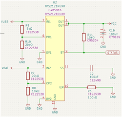
VPR1 = VUSB * (R10 / (R10 + R9))
VPR1 = 5V * (20 / (20 + 5))
VPR1 = 4V
VCP2 = VBAT * (R8 / (R8 + R7))
VCP2 = 9V * (10 / (10 + 20))
VCP2 = 3V
FACTS
If VPR1 > VCP2 IN1(VUSB) is powering output.
If VPR1 < VCP2 IN2(VBAT) is powering output.
If VCP2 > VREF(1.06V) fast switchover mode is enabled.
SCENARIO 1 (VBAT & VUSB PRESENT)
VUSB (IN1) = 5v
VBAT (IN2) = 9v (fully charged)
VPR1 = (5 * (20/(20 +5)) = 4V
VCP2 = (9 * (10/(10 + 20)) = 3V
VPR1 (4V) > VCP2 (3V) so IN1(USB) is powering output.
VCP2 (3V) > VREF (1.06V) so FAST SWITCHOVER MODE
Low battery voltage makes no difference as VPR1 is always greater than VCP2
as VCP2 drops with battery depletion.
SCENARIO 2 (VBAT PRESENT & VUSB DISCONNECTED)
VUSB (IN1) = 0v (Disconnected)
VBAT (IN2) = 9v (fully charged)
VPR1 = (0 * (20/(20 +5)) = 0V
VCP2 = (9 * (10/(10 + 20)) = 3V
VPR1 (0V) < VCP2 (3V) so IN2(VBAT) is powering output.
VCP2 (3V) > VREF (1.06V) so FAST SWITCHOVER MODE
SCENARIO 3 (VBAT DISCONNECTED & VUSB PRESENT)
VUSB (IN1) = 5v
VBAT (IN2) = 0v (Disconnected)
VPR1 = (5 * (20/(20 +5)) = 4V
VCP2 = (0 * (10/(10 + 20)) = 0V
VPR1 (4V) > VCP2 (0V) so IN1(VUSB) is powering output.
VCP2 (0V) < VREF (1.06V) FAST SWITCHOVER DISABLED
SCENARIO 4 (VBAT & VUSB PRESENT then VUSB DISCONNECTS)
This starts as scenario 1 with
- IN1 (VUSB) is powering the output.
- Fast Switchover mode is enabled.
When VUSB is removed then we are in scenario 2
- IN2 (VBAT) is powering the output.
Because fast switchover was enabled then this should have
minimal voltage drop, especially with C16 100uf COUT cap.
Have i understood correctly? Anything i have missed or miscalculated? Many thanks in advance.
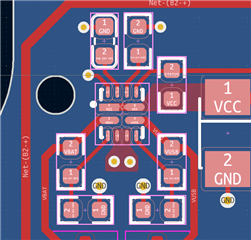
Layout for reference: