This thread has been locked.

If you have a related question, please click the "Ask a related question" button in the top right corner. The newly created question will be automatically linked to this question.

LM234: Lm234 application

Part Number: LM234


Tool/software:

Hello,

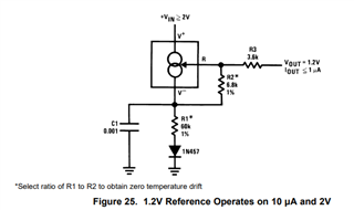
I am examining a circuit that uses the LM234, and it is utilized in the way I marked in the schematic. When I reviewed the application notes, I couldn't find such a usage. Could you help me understand this?

Thank you in advance for your assistance. I look forward to your recommendations.

  • Hi Murat,

    Thank you for your question!

    Can you provide more context to the application/use case for this circuit?

    Two things I notice are the GND connection to the left of the 3K resistor and the orientation of the LM234. This example seems a bit similar to Figure 25 from the datasheet (shown below) but the output is grounded and the LM234 is reversed. Generally, current flows from V+ to V-, but this circuit seems to try and do the opposite.

    Could it be that some of the components could also be marked as unpopulated on the schematic?

    Please let me know if there is any additional context to this circuit, and I hope this helps!

    Best Regards,

    Andrew Li

  • Thanks for your answer. This is whole schematic.

    Best Regards.

  • Hi Murat,

    Thanks for sharing the whole schematic!

    Can you also provide some more information about the application of the circuit?

    One thing that I find a bit strange about this circuit is the direction of the LM234. Generally, current is supposed to flow from V+ to V-, but this configuration seems to conflict with itself as the diode is opposite the direction of V+ to V-.

    It does seem like Figure 25 from the datasheet but with slight changes such as the grounding of the reference pin and the opposite direction of the LM234.

    For further support, could you please provide some information about what this circuit tries to achieve and its intended application?

    Best Regards,

    Andrew Li

  • It is related with NAMUR and L-Bus comminication. 

  • Hi Murat,

    Thank you for providing some additional context!

    It seems that the LM234 is acting as a temperature dependent current source in this situation. The voltage at node V_R in the schematic you sent depends on the temperature of the system, and this will inject current upward into the system (out of the V- terminal) if the above voltage becomes too low. Below is a screenshot from the datasheet detailing the relationship between V_R and temperature.

    The diode placed beneath the LM234 (screenshot below) seems to act as a protection against too much current injection into the rest of the circuit since it will turn on if the voltage at the + pin of the LM234 is high.

    I hope this helps!

    Best Regards,

    Andrew Li