This thread has been locked.

If you have a related question, please click the "Ask a related question" button in the top right corner. The newly created question will be automatically linked to this question.

TPS61235P: Unstable Operation of the IC

Part Number: TPS61235P

Tool/software:

Hello there,

I am trying to build a 18650 li ion battery powered LED lighting system, the LEDs consume 1.3A as a board. I used TPS61235P for boosting the input level and did my calculations on 5.1V fixed supply.

I use transistor low side switching topology in my circuit powered all by the boost converter. The output voltage level of the IC is 5.2V and when the load is connected it reduces to around 5.143V. It works okey in 3.3V-4.2V of the battery voltage but when it discharges to 3.2V it gets in probably pre-charge phase because then the LEDs blink in long off time period. I think the sensing topologies inside of the IC is affected due to abnormal operation of the IC. I tried to give the 5.1V from outside of the board and used boost converter for just supplying the MCU therefore switching the FET, it worked as expected. Without any problems. I shorted the CC pin to AGND but that is not the solution.

Overall as much as i increase the load current as soon as it behaves abnormally.

Then I checked the design;

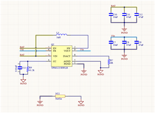
It is aimed to get 3A output current 

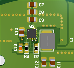
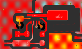
This is the top layer and the feedback pin is shorted to the output (5.1V)

Heres the mistake i've done I think because the feedback line is shorted to the output Polygon. 

Could this be the reason of 5.2V output instead of 5.1V fixed? Thanks.

Regards,

Kaan

  • Hi Kaan,

    So I assume that your question is why the output voltage is 5.2V when the load is not connected? 

    When the load is not connected, the device operates at PFM mode, so the typical target output voltage is 5.2V, as you can see it is in the datasheet.

    After the load is connected, if the load current is up to 3A, the device will operate at PWM mode, the output voltage reduces to 5.1V.

    Hope this can answer your question.

    Regards,

    Nathan

  • Hey Nathan,

    Thanks for the answer. 7mA load is always connected is that not sufficient enough to switch the device into PWM mode?

    When the battery voltage reduces to 3.3 - 3.2V and the desired current around 1A the output reduces its voltage to near input level 300 - 400mV higher. When the output current is reduced to 300mA the device can get down until 2.9V the rest is the same story.

    Increasing the load current results the device gets in pre-charge (assuming) mode even in higher voltages as 3.7 - 4V

    In this case I can only use the battery until 3.4V discharged. Is this the performance of TPS61235P?

    Regards,

    Kaan

  • Hi Kaan,

    Yes, 7mA is too small to enter into PWM mode.

    So do you mean that the output voltage is much lower than 5.1V when battery voltage is ~3.3V and the load current is ~1A?

     It should not be the expected behavior of TPS61235P, could you please double check the VIN pin voltage of TPS61235P in this condition? I am not sure if there is a large voltage drop between battery and the VIN of TPS1235P.

    Or it would be also very helpful if you could share any oscilloscope screenshot of like VIN, SW, VOUT with us to analyze.

    Regards,

    Nathan