UCC23514: 3.3V buffer for opto-compatible gate driver

Part Number: UCC23514
Other Parts Discussed in Thread: UCC5350

Tool/software:

Hi,

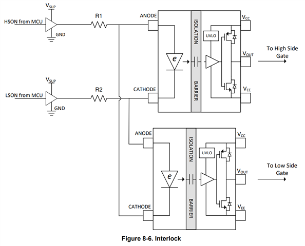
What kind of buffer would you recommend for driving UCC23514 in interlock arrangement? We have only 3.3V and 24V supplies available. The problem with most logic is that VOH is around 2.4V at minimum while VF max of UCC23514 is 2.4V as well.

So are there some sturdy enough 3.3V buffers available or should we use a gate driver to drive the gate driver from 24V?
 

BR,

Olli

  • Hi Olli,

    The input to the UCC23514 is a diode. You should aim to deliver about 10mA into a voltage of about 2.1V to turn the output "ON". If your microcontroller output is 3.3V, you will need 120 Ohms in series from 3.3V to conduct 10mA of current from 2.1V.

    In an interlock circuit, only one device will be "ON" at a time. Most GPIO pins can supply 10mA of current without a buffer. If there is a long distance, you might want to add a local capacitor across ANODE and CATHODE to filter noise at the gate driver input.

    You can use a buffer such as SN74LVC1G126DCKT between the microcontroller's GPIO pin and the anode of the UCC23514 to deliver more current and shorten the trace length. It is not strictly necessary.

    If you use a 24V gate driver, you will need a 22k resistor to allow 10mA to drop 22V into the 2V diode input.

    Best regards,

    Sean

  • Hi Sean,

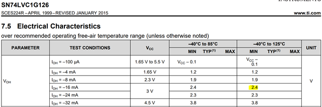
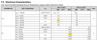
    Thanks for the answer. However, I think my problem was not fully understood. If you look at the datasheet of SN74LVC1G126DCKT, you can see that the output can swing only up to 2.4V at 16mA output and 3.0V supply. We could then assume that the voltage drop of the logic output is about 0.6V over the  3.0...3.3V range.


    Recommended IF range for UCC23514 is 7 mA to 16 mA. With 5% tolerance at 3.3V supply, the maximum series resistance would be (0.95*3.3V-0.6V-2.4V)/7mA=19 ohms. If the logic voltage drop would be only 0.5V (considering lower current), the resistance would be 33 ohms. Now let's calculate the maximum current at maximum VCC and minimum VF (VOH still at minimum): (1.05*3.3V-0.5V-1.8V)/33ohm=35mA which is much higher than the abs.max. rating of UCC23514.

    BR,

    Olli

  • Hi Ollie,

    19 ohms is too low. Using your equation, if Vcc=3.135, the loaded output voltage would be -0.6 and 2.535V. You would need a 62 ohm resistor for 7mA to bring the voltage down to 2.1V at the anode. 

    You are using the absolute minimum Voh value over temperature for this calculation. They typical output voltage will not droop by 0.6V. You can treat the output as an additional 20 ohms to the rail. It will add some error to your resistor calculation, but there is a 7mA-16mA input current tolerance range and the resistor accuracy is not that important.

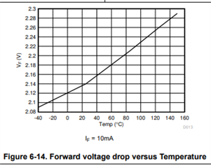
    At extreme temperatures you will have a lower diode voltage too. The effects might cancel out. If your circuit is running that hot, you will have bigger problems!

    Best regards,

    Sean

  • Hi Sean,

    When developing reliable electronics I can't rely on typical values or hope that the effects might cancel out. I would need to find a way to calculate the current to be at acceptable level based on datasheet values with all tolerances over the temperature range taken into consideration. If that is not possible with 3.3V logic and UCC23514, do you have any other suggestions?

    BR,

    Olli

  • Hi Olli,

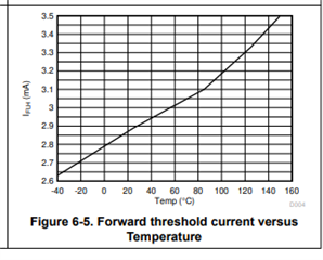
    The If vs. temperature and Vf vs. temperature tolerances are in the datasheet, and I have copied them here:

    I still would like to convince you that 3.3V logic that can supply 20mA is sufficient to drive the UCC23514 input. We just need to confirm the corner cases still work if we design for a 10mA typical input current.

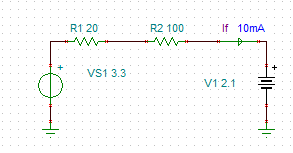
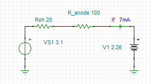
    If the supply is 3.3V typical, and we need 120 ohms in series to supply 10mA into 2.1V at room temperature. If we treat the output resistance of the logic output as 20 Ohms, then we only need 100 ohms of resistance.  

    If the supply droops to 3.1V, and the temperature increases to 120C, then there should still be 7mA of input current, which is well above the 3.3mA threshold at 120C. 

     Optotron_If.TSC

    If you design for the typical values, and you know which direction thresholds will move with temperature, you can ensure that your design stays functional across the whole operating range. 

    Best regards,

    Sean

  • Hi Sean,

    Thanks for your effort. I'm still not convinced that you can safely approximate 74LVC output to be voltage source with 20ohm impedance. Calculating with the datasheet values of 2.4V VOH at Vcc=3V and IOH=-16mA it would indicate the Rdson of the PMOS transistor to be ~ (3V-2.4V)/16mA=37.5ohms at maximum. For NMOS 0.4V/16mA=25ohms. Then, in interlock arrangement we have two logic outputs effectively in series. So in total, 37ohm+25ohm=62ohm at maximum. But now we don't know the minimum as VOH max and VOL min are not specified. I suspect 50% of maximum is quite close?

    So the external resistance should be (at 85degC): (3.1V-2.3V) / 7mA - 62ohm = 52ohm. I'm using 2.3V as max VF as there are some tolerances as well in addition to temperature effects. 

    Now if we check the cold ambient with VCC=3.5V, 50% reduced Rdson of the logic output and VF of 1.8V: IF=(3.5V-1.8V)/(62ohm*0.5+52ohm)=20mA. 

    So yes, it seems like the math could work. However, the margins are quite small so we have to consider if we want to do it like this or use UCC5350 instead.

    BR,

    Olli