This thread has been locked.

If you have a related question, please click the "Ask a related question" button in the top right corner. The newly created question will be automatically linked to this question.

TPS23523: Design review

Part Number: TPS23523
Other Parts Discussed in Thread: , CSD19535KTT, CSD19532Q5B

Tool/software:

Hello,

My customer requests TI's review of the TPS23523 design.

Please review the following:

TPS23523_review_241108.pdf

Q1. Please check to see if there is a problem with that customer's circuit.

Q2. The TPS23523EVM-863 user guide lists the current limit setting as 12.5A. According to the circuit design of the EVM, ICL1 = VSNS,CL1 / RSNS = 40mV / 2mohm = 20A. Please tell us how to calculate 12.5A.

Q3. The SNS pin of EVM is connected to VEE through 100ohm. Please tell us why this connection is needed.

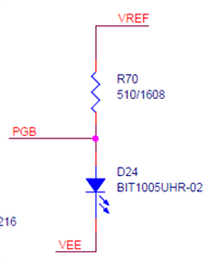
Q4. Could you please advise if the PGB pin connection circuit below is ok?

Q5. Based on 100W load, would it be okay to change the FET (CSD19535KTT) connected to GATE to the FET (CSD19532Q5B) connected to GATE2? For this, are there any additional factors to consider besides the power and current of the FET?

Thanks in advance.

JH

  • Hi JH,

    I will review and get back by early next week.

    Best Regards,

    Rakesh

  • Hi Rakesh,

    Thanks for your help. I would appreciate it if you could share updates on the customer inquiries.

    BRs,

    JH

  • Hi JH,

    1A) Schematic looks fine

    2A) If we leave PROG pin, the device sets VSNS,CL1 as 25mV which gives 12.5A 

    3A) R12 and R17 in the EVM forms a voltage divider to reduce the effective sense resistor seen by the device. 

    the Rsense effective =  R21 * R12/ (R12+R17)

    4A) use as per EVM schematic if you are using PGB  to control downstream load

    5A) As it is 5A design, you can use lower SOA FET. please use design calculator to verify the design

    Best Regards,

    Rakesh