Tool/software:
Hi Expert,
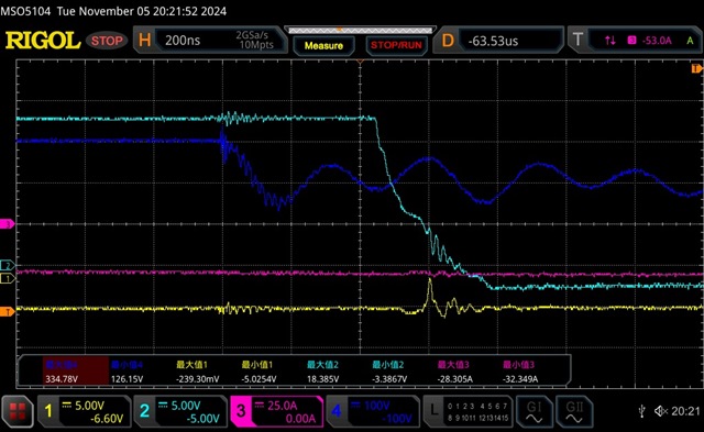
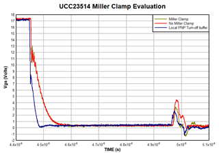
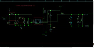
My customer is using UCC5350, but clamping function couldn't work normally. here is the schematic and wave. please help to review
Br
Chi
Tool/software:
Hi Expert,
My customer is using UCC5350, but clamping function couldn't work normally. here is the schematic and wave. please help to review
Br
Chi