This thread has been locked.

If you have a related question, please click the "Ask a related question" button in the top right corner. The newly created question will be automatically linked to this question.

UCC28740: Feedback Loop Design Considerations for Flyback Converter

Part Number: UCC28740
Other Parts Discussed in Thread: TL431,

Tool/software:

Hi E2E

I am referring to your application note - Practical Feedback Loop Design Considerations for Flyback Converter Using UCC28740 and have the following queries. 

1. I understand the basic operation of the optocoupler with TL431-based feedback, but what is the significance of ROPT, and why it is required?

2. Why are CFB and CFB3 in feedforward mode, how does it differ, if feedforward vs feedback capacitor here for TL431 and opto coupler?

3. Significance of having COPTO?

Thanks in Advance 

Best

Chaitanya 

  • Hello,

    Your inquiry has been received and is under review.

    Regards,

  • Hello,

    Please see my comments below.

    I am referring to your application note - Practical Feedback Loop Design Considerations for Flyback Converter Using UCC28740 and have the following queries. 

    1. I understand the basic operation of the optocoupler with TL431-based feedback, but what is the significance of ROPT, and why it is required?

    > This is basically to ensure the TL431 has enough current to always be active.

    >I believe the TL431 needs a bias current of 1 mA to operate so Ropto should be 680 ohms.

    >Vd opeto = 0.7v, IRopt = 0.7V/680 ohms = 1.03 mA.

    2. Why are CFB and CFB3 in feedforward mode, how does it differ, if feedforward vs feedback capacitor here for TL431 and opto coupler?

    > These capacitors are feedback compensation capacitors and are all in the feedback loop.

    > Traditional compensation would have all the feedback components on the secondary side of the TL431.

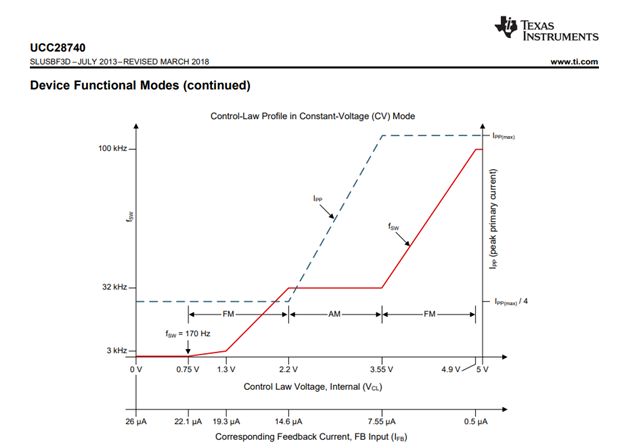
    > The UCC28740 controls the peak current and control switching frequency based on feed back current coming out of the feed back pin.  Which required a non traditional type to compensation to compensate the feedback loop.  


    The application note you are referencing was written to show you how to compensate the voltage loop with this non traditional feedback method to achieve a stable design.  

    3. Significance of having COPTO?

    It is not uncommon for designers to put a capacitor across the opto isolator collector and emitter.  This in generally done to suppress noise in the system.

    I think this is a carry over from traditional feedback designs where the emitter is ground reference, where this opto isolator configuration is not.

    Thank you for interest in Texas Instruments (TI) products.  If you have a related question, please click the "Ask a related question" button in the top right corner. The newly created question will be automatically linked to this question.

    Regards,