This thread has been locked.

If you have a related question, please click the "Ask a related question" button in the top right corner. The newly created question will be automatically linked to this question.

TPS25751EVM: Design suggestions for the TPS25751EVM+BQ25756EVM

Part Number: TPS25751EVM
Other Parts Discussed in Thread: BQ25756EVM, TPS25751, , BQ25756, EV2400

Tool/software:

Hi TI Support


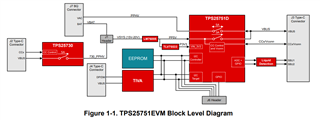
I have successfully managed to get the combination of the TPS25751EVM + BQ25756EVM working together as per section 4.2.1.1 of the  "EVM User's Guide: TPS25751EVM TPS25751 Evaluation Module". This is a big milestone for the project which is great.


However I have found that the combined pair of boards is rather "closed" and I can't see what is going on via any of the debug tools (Battery Management Studio in particular). I believe that this is because the TIVA microcontroller on the TPS25751EVM board is controlling the I2C line which would be traditionally be used by the EV2400 controller for the BQ25756. Ultimately I want to connect up an external micro controller to control the various modes and registers of both the USB and battery charging chips.

Therefore could you please suggest how would be the best way to either

i) expose an interface so that I can see what is going on in the two boards using one of the existing TI tools

OR

ii) configure the boards so that I can connect an external microcontroller so that I can control the BQ25756 & TPS25751 chips directly

Another thought I had was whether it would be possible to reprogramme the TIVA microcontroller and use that as the starting point for my project......

All thoughts, comments, design suggestions would be really appreciated! Thank you for your time.

Regards


Richard

  • Hi Richard, 

    the TIVA microcontroller on the TPS25751EVM is purely for flashing the configuration from the GUI directly to the EERPOM. It does not serve any other function during run-time. 

    i) expose an interface so that I can see what is going on in the two boards using one of the existing TI tools

    OR

    ii) configure the boards so that I can connect an external microcontroller so that I can control the BQ25756 & TPS25751 chips directly

    On the TPS25751EVM, there are I2C pins expose on J6 header. I2Ct_SDA/SCL are connected to TPS25751 for the PD controller acting as the I2C target (slave) device while the I2Cc_SDA/SCL are for TPS25751 acting as the I2C controller (master) device. The I2Cc_SCL/SDA lines also have BQ25756 and the EEPROM on the same bus line. The I2Ct_SCL/SDA lines are connected to the TIVA but as mentioned before, the TIVA does not serve any other function besides writing to the EEPROM. You can connect the I2Ct lines to your own MCU for development purposes or connect I2Cc to the EV2400 to read BQ25756 registers through Battery Management Studio. 

    Here is a screenshot of the TPS25751EVM block diagram showing where all the I2C nets are connected to: 

    Let us know if you have any further questions or concerns! 

    Thanks and Regards,
    Raymond Lin

  • Thank you - that's really helpful....