Other Parts Discussed in Thread: TPS53667
Tool/software:
I recently used TPS53667EVM-769 to measure the small signal models, and encountered some confusion about the ramp value and waveform.
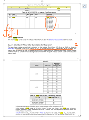
1、The datasheet indicates that MFR14 can set the ramp value(show in fg.1), but it also suggests that the resistor RocL from OCL_R pin to Vref. Which value, the ones given in fusion designer or the external resistor RocL determines the ramp value?
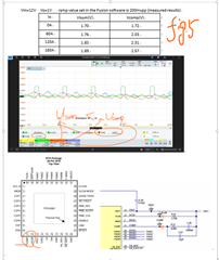
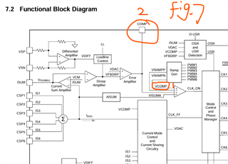
2、If it is the one given in fusion designer that determines the Vramp value, it means that the Vcomp value would change as the MFR value is changed from 20mV to 200mV( fig.2), However, we found this was inconsistent with the actual waveform, that is, the Vcomp didn’t change when the MFR value is changed during the experiment.
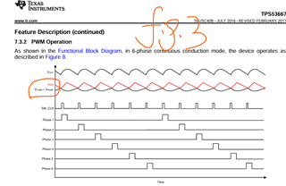
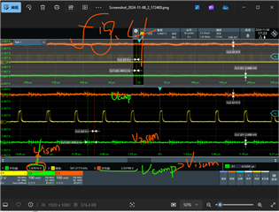
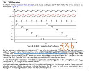
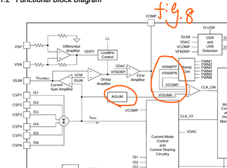
3、As the datasheet shows Visum≈Vcomp+Vramp (fig.3). It means that the Vcomp value should be less than the Visum value, but the actual waveform shows that Vcomp > Visum (fig.4), and the difference between them is different under different loads. So what does the actual waveform of the Vramp look like?