This thread has been locked.

If you have a related question, please click the "Ask a related question" button in the top right corner. The newly created question will be automatically linked to this question.

bq27000: does GND & GND_PACK order (topology) matter?

Anonymous
Anonymous
Other Parts Discussed in Thread: BQ27000, BQ26221, BQ26200, BQ27500

Hi,

I would like to ask a question on bq27000.


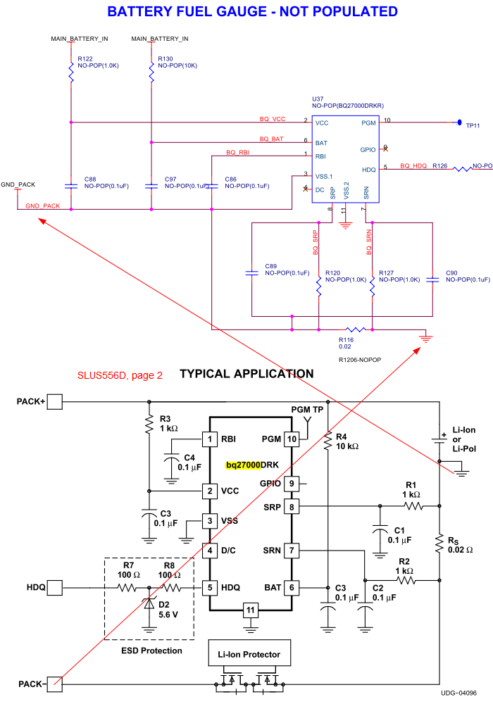
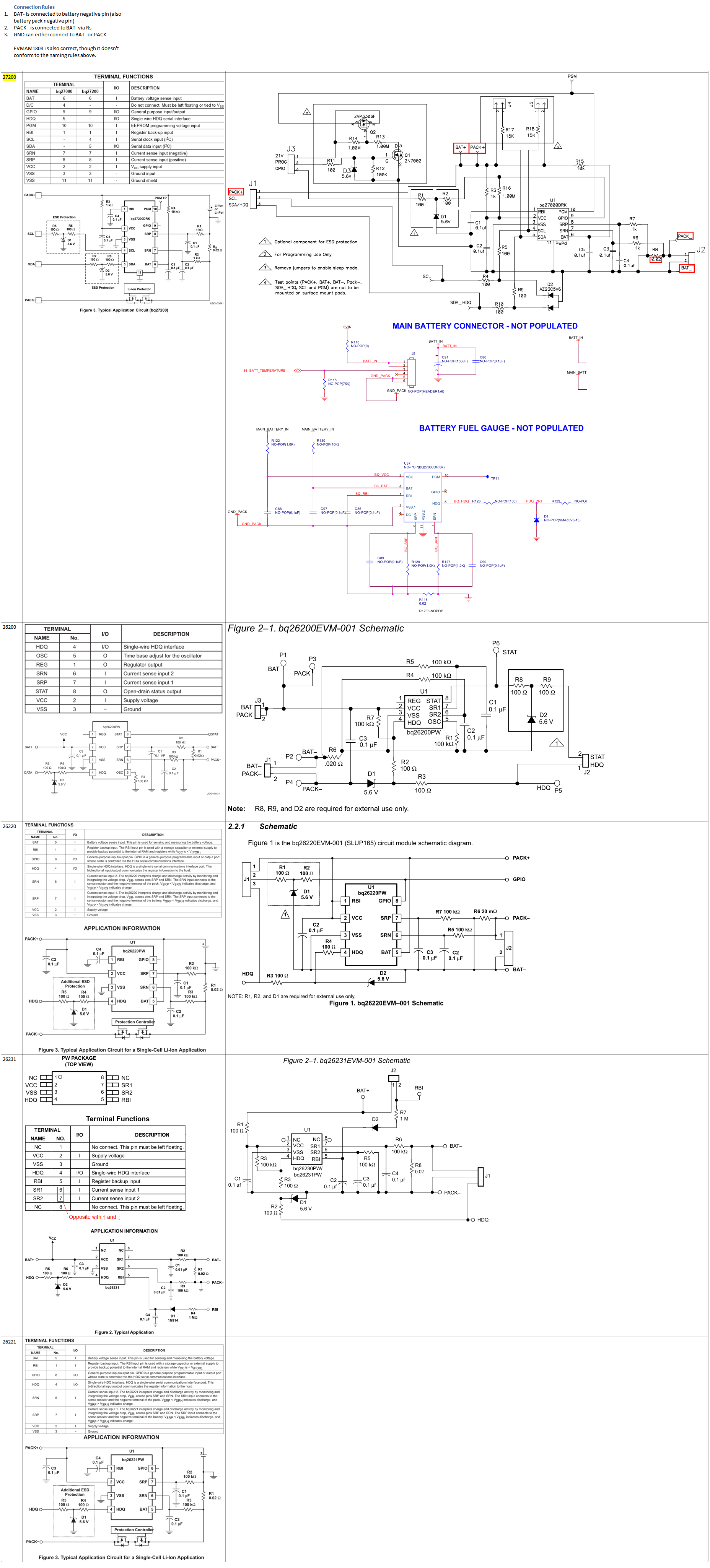
In sheet 37 of EVMAM1808 schematics from TI partner SpectrumDigital, bq27000

  • [SRP, 8, positive current sense input] is connected to GND_PACK
  • [SRN, 7, negative current sense input] is connected to GND

This is the opposite from page 2 of bq27000 datasheet SLUS556D. Is this an error in EVMAM1808 schematics design here?


Zheng


  • Zheng,

    The first image above is erroneous in that pins 3 and 11 of the bq27000 are shorting ground across the sense resistor. Its possible that the ground symbol used on the SRN side may be a system ground different from ground pack. The correct way is that pin 3 and 11 should be tied together and not separated by sense resistor. There is not a wrong side of the sense resistor for you tie the bq27000 Vss. If you tie it on the SRN side then you just pick up the voltage drop across sense resistor into the battery voltage measurement.

  • Anonymous
    0 Anonymous in reply to MikeV

    Mike,

    Thanks for the answer.

    I am still looking at this and some battery literature. I will come back to this topic some time later.


    Zheng

  • Anonymous
    0 Anonymous in reply to MikeV

    Mike,

    I compared bq27000/27200 datasheet connection with its EVM, SpectrumDigital EVMAM1808, datasheet and EVM of {bq26200, 26220, 26231}, and datasheet of bq26221 alone. I saw a set of rules, with the exception of EVMAM1808, that all connection examples conform to. EVMAM1808 differs slightly with net naming perhaps since it is not designed internally within TI, but electronically it is also correct. I initially thought it was incorrect because it looks different from bq27000/27200 example, and now I found it is correct.

    Connection Rules

    1.       BAT- is connected to battery negative pin (also battery pack negative pin)

    2.       PACK-  is connected to BAT- via Rs

    3.       GND can either connect to BAT- or PACK-

    EVMAM1808 is also correct, though it doesn't conform to the naming rules above.


    Old:

    GND, which is usually the digital ground of the connected system, can connect with either BAT- or PACK-. Because |VSRN-VSRP| = |Isystem total ∙ RS(0.02Ω)|, if we assume the peak total system current is smaller than 2A, then |VSRN-VSRP| < 40mV. So connect GND to BAT- or PACK- could only result in 40mV or ±20mV voltage change. If there is no LDO regulator working with output-input voltage difference on the verge of the 100mV minimum drop-out, then this 40mV difference would not affect other parts of the system.

    New:

    The net denoted by the three short horizontal line with tapering width, namely the identical symbol used conventionally as the "GND" net, has been used without duly consideration to avoid ambiguity when this "GND" and BAT- net are connected together.

    The three short horizontal line with tapering width denotes actually only the ground of the battery gas gauge, not the ground of the whole system. If the ground of the whole system is connected directly to BAT-, then clearly PACK- will be bypassed, and there will be no current flow through RS and hence no way to measure RS's voltage drop. The ground of the whole system with the exception of the battery gas gauge should be connected to PACK-, then all current will flow through RS for the measurement to be valid.

    Simply speaking, all datasheet and EVM (except SpectrumDigital EVMAM1808) connection examples shown here made the notational mistake of confusing ground of the system with the ground of the battery gauge by using the same symbol.

    As for rule 3 "GND can either connect to BAT- or PACK-", I reckon that it is better for GND (battery gas gauge ground) to be connected with PACK-, so that the current(energy) flow through the battery gas gauge itself can also be measured. Though this current is very small as for example bq27x00's maximum active current is only 90 µA, it is still better to have it counted both for a very slight improvement in gauging precision and for making the circuit looks more "visually correct" and comfortable.

    Also according to this updated discussion above, the ground of the remaining system parts should always be connected to PACK-, so whether connecting battery gas gauge ground to BAT- or PACK- would not affect LDO voltage drop-out considerations.


    A compilation of the comparisons mentioned is shown in the image below. IE seems doesn't support opening the image alone in another window or tab, so it might need to be saved on disk and open with another image viewer due to its size; Firefox can "View Image" directly from the context menu.

    I still wish to get a confirmation for my result for added assurance.


    Zheng

  • Zheng,

    Not all schematics are done by the same person or company for which you can't necesarilly expect that references are made with identical intentions. I want to refer to the schematic on the top right of the image that you attached in this posting. If you take that schematic for example you will notice that it doesn't have a ground symbol. Ground symbol is used differently by engineers. It is just a way to establish a reference from which you expect to compare single point voltage at any given node in a system. Regardless of whether you use a ground symbol or not the schematic that I'm referring to represents how you should be making connection of the gas gauge to a battery cell in which the cell end are denoted by BAT+ and BAT_. In this case the system and charger connect to the board across PACK+ and PACK_ connections.

    As for where to place the VSS of the gauge our schematics show where we recommend to place it but technically it could be placed at Pack- or if you had a Low-side FET protector IC then it could be placed between the sense resistor and the FETs.

  • Anonymous
    0 Anonymous in reply to MikeV

    Mike,

    MikeV, 2nd post of this thread said:

    If you tie it on the SRN side then you just pick up the voltage drop across sense resistor

    into the battery voltage measurement.

    It seems that if I am tying both [pin 3] and [pin 11] on the SRN side, then the voltage measured will be the actual battery voltage less the voltage across RSENSE. Correct?


    Although (1) bq27x00 datasheet example show connecting [pin 3] and [pin 11] together, the "Terminal Functions" describes [pin 3] as ground "input" and [pin 11] as ground "shield". What is the different between ground "input" and ground "shield"? Are [pin 3] and [pin 11] still the same pin?


    Zheng

  • Anonymous
    0 Anonymous in reply to MikeV

    Mike,

    I follow your stipulation and refer all nets below to the top right image:

    MikeV said:

    As for where to place the VSS of the gauge our schematics show where we recommend

    to place it but technically it could be placed at Pack- or if you had a Low-side FET protector

    IC then it could be placed between the sense resistor and the FETs.

    So you baiscally mean: In principle, the ground of bq27x00 could be connected to the internal of the battery back, between the true negative end of the Li-ion/Li-Pol cells and the protection IC, as in your reply to "bq27x00 datasheet: GND and PACK- connection"

    MikeV said:

    The application schematic is correct. The ground symbol should not be confused with the

    Pack- connection. The VSS of the gauge is connected typically to the negative node of the

    cell. Pack- is the most negative reference that the connecting system has access to. The

    Cell- and the Pack- are offset by the protector ICs FETs and the sense resistor,

    However, you are aware of the fact that not all battery manufacturers expose connections further beyond PACK- to the internal of the battery pack (beyond protection IC), so in this case there is no way to connect bq27x00 [pin 3] and [pin 11] to the negative node of the cell. Then as an alternative, [pin 3] and [pin 11] might also be connected to "most negative reference that the connecting system has access to", namely the PACK- in the datasheet example (top 2nd left image).

    Comparison:

    bq27x00 [pin 3] & [pin 11]

    V(BAT PIN, 6)-V(VSS PIN, 3& 11)

    to cell negative

    True cell voltage

    to pack negative

    Cell voltage less VR(SENSE)


    Are the characterizations above correct?


    Zheng

  • To further confirm that the VSS and in that case even the sense resistor can be placed at the BAT- or outside the Pack-. There are gas gauge implementations which are referred to as system side gas gauges and they are contained inside the system and not the battery. These gauges actually share the same ground with the system,

  • Anonymous
    0 Anonymous in reply to MikeV

    Mike,

    Could you give an example schematic of a "system side gas gauge"?


    Zheng

  • Refer to www.ti.com website for products such as bq27500, bq27505 and bq27520.

  • Anonymous
    0 Anonymous in reply to MikeV

    Mike,

    I can confirm now that your answers are correct. I appreciate your detailed and helpful explanations.

    Zheng