This thread has been locked.

If you have a related question, please click the "Ask a related question" button in the top right corner. The newly created question will be automatically linked to this question.

LM234: 2.5 µA Current Source Application

Part Number: LM234


Tool/software:

Hello There,

I need a current source for a sensor application that requires 2.5 µA of I sink. I assembled the circuit on a breadboard, but it isn’t working properly. Could you please help me check if the circuit below is correct?

Spec
Iset=2.5uA
VREF = 4.1V
Load 10K~1M 


Thanks! 
Rene

  • Hi Rene,

    Thanks for your question!

    It looks like you are trying to implement a zero temperature coefficient current source. Can you provide some more information about the result you are seeing on the breadboard? What do you mean when you say it is not working properly?

    Best Regards,

    Andrew Li

  • Hi Andrew,

    Thanks for your reply.

    I am not getting 2.5 V; instead, I'm measuring 41 mV with a 1 MΩ load. The circuit I showed you should be working correctly, right? I will troubleshoot to see if I misconnected something.

    Best Regards,

    Rene.

  • Hi Rene,

    Thanks for the additional information.

    When you say 2.5 V and 41 mV, do you mean 2.5 uA of current, or which node are you expecting 2.5 V but only measure 41 mV on?

    Best Regards,

    Andrew Li

  • Hi Andrew,

    There was a misconnection in my assembly. Now it works, but I measured 2.12V across the LOAD (1M ohm). Considering a maximum error of 9% (8% from the IC + 1% from the resistor), I should be reading around 2.3V, right? Did I miss something?

    Thanks.

    Rene.


  • Hi Rene,

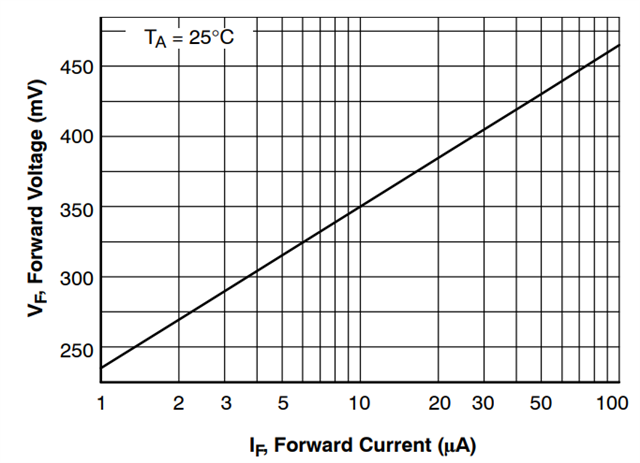
    For your application of 2.5 uA, the MMBD1201 diode has a smaller forward voltage drop than the utilized diode in the zero-tempco current source example in the LM234 datasheet. Below is a screenshot of the MMBD1201's datasheet:

    Since the forward voltage at 2.5 uA is lower than the example's 0.6 V drop, this could be the cause of what you are seeing on the breadboard. Adjustment of R1 and R2 may be necessary to accommodate this change if desired.

    I hope this helps!

    Best Regards,

    Andrew Li

  • Hi Andrew,

    Thanks a lot for your replay.

    I just need to change VDV_DVD from 0.6 to around 0.275 to adjust R1R_1R1 and R2R_2R2 correctly, right?


    Regards,
    Rene.

  • * I just need to change VD from 0.6 to around 0.275 to adjust R1 and R2 correctly, right?

  • Hi Rene,

    Yes that is correct.

    If you need further support, please let me know!

    Best Regards,

    Andrew Li